In the framework of Industry 4.0, where smart manufacturing demands high-precision 3D processing, multi-material compatibility, and unmanned operation, the automated 3D laser cutting robot arm machine has emerged as a core production tool. Unlike
2D laser cutters (limited to flat sheets) or manual 3D cutting (prone to error), this system integrates 6-axis robotic motion control, high-energy laser sources, and intelligent 3D vision guidance to solve key pain points in modern manufacturing—such as complex curved surface processing, low efficiency of multi-setup operations, and poor batch consistency. It is widely used in high-value sectors requiring precision, including aerospace, automotive, and medical devices, and complies with international standards such as ISO 230-2 (positional accuracy) and ISO 10110 (laser processing quality). Below is a technical analysis of its core components, operational mechanisms, technical advantages, industry applications, and future development.
1. Technical Definition & Core Component Specifications
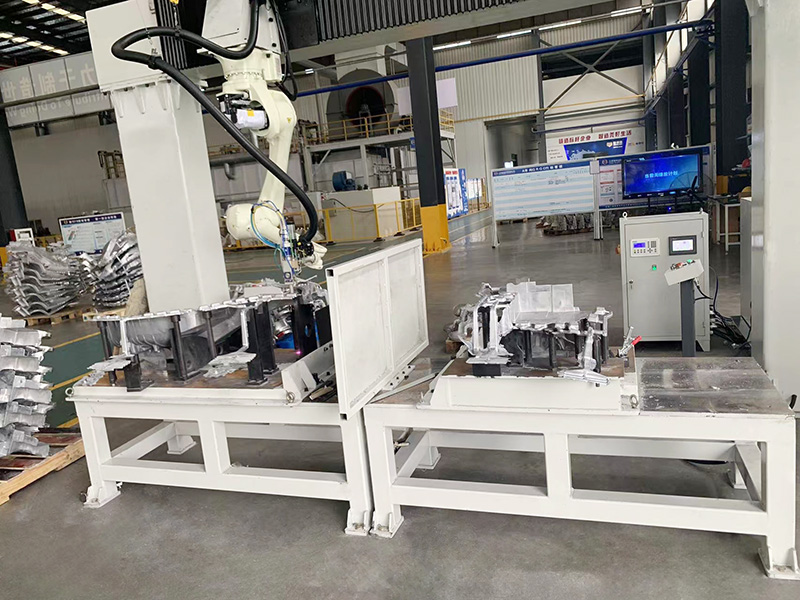
An automated 3D laser cutting robot arm machine is an integrated system designed for non-contact 3D material cutting. Its performance is determined by three core subsystems, whose technical parameters directly dictate processing accuracy and efficiency:
| Core Subsystem | Technical Details | Function |
|----------------------|----------------------------------------------------------------------------------|--------------------------------------------------------------------------|
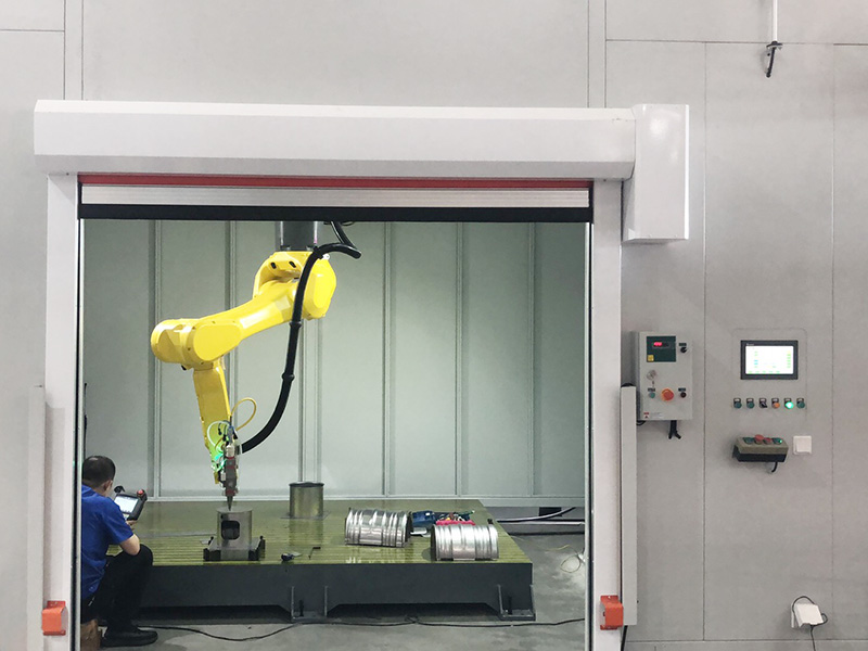
| 6-Axis Robotic Arm | - Axis configuration: X/Y/Z (linear) + A/B/C (rotational)<br>- Repeatability: ±0.005–0.01 mm<br>- Maximum reach: 1.2–3.5 m<br>- Payload: 30–200 kg (for laser head + vision module) | Manipulates the laser head to follow 3D cutting paths, ensuring the laser beam remains perpendicular to the workpiece surface (even for curved/undercut features). |
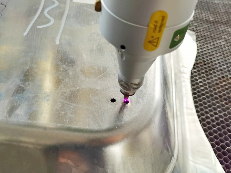
| Laser Cutting Module | - Types: Fiber laser (1060–1080 nm), CO₂ laser (10.6 μm), disk laser (1030 nm)<br>- Power range: 1kW–50kW<br>- Beam quality (M²): <1.2 (fiber/disk lasers), <1.5 (CO₂ lasers)<br>- Focus spot size: 0.05–0.5 mm | Converts electrical energy into high-density laser beams (10⁵–10⁷ W/mm²) to melt, vaporize, or ablate materials, achieving burr-free cuts. |
| 3D Vision Guidance System | - Technology: Structured light / laser triangulation<br>- Scanning accuracy: ±0.02 mm<br>- Point cloud resolution: 0.1 mm/point<br>- Compatibility: Supports CAD file formats (STEP, IGES) | Scans the workpiece to generate a 3D point cloud, compensating for positional deviations (e.g., ±0.5 mm workpiece placement errors) and optimizing cutting paths in real time. |
2. Operational Mechanism & Technical Workflow
The system’s high precision and automation rely on a closed-loop workflow that integrates “3D perception → path planning → dynamic execution → real-time monitoring.” Each step is optimized for 3D cutting scenarios:
Step 1: 3D Workpiece Scanning & Data Processing
- The 3D vision system (e.g., Keyence LJ-V7000, Basler blaze) scans the target workpiece, capturing geometric data (e.g., curved surfaces, holes, notches) to form a high-resolution point cloud.
- Software (e.g., Halcon, Siemens NX) processes the point cloud to:
1. Align the actual workpiece with the CAD model, calculating compensation values for placement errors (e.g., ±0.3 mm offset).
2. Identify critical features (e.g., undercut edges, inclined planes) that require adaptive laser head orientation.
Step 2: Offline Programming (OLP) & Path Optimization
- Using OLP software (e.g., ABB RobotStudio, Fanuc ROBOGUIDE), engineers pre-design 3D cutting paths based on the processed point cloud:
- The software automatically optimizes the robot’s motion trajectory to minimize travel time (reducing cycle time by 15–20%).
- For thin-walled workpieces (≤ 3 mm), it adjusts laser parameters (e.g., pulsed mode: 5–10 kHz frequency) to prevent burn-through.
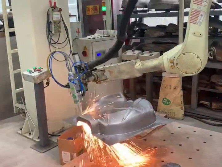
Step 3: Dynamic Cutting Execution & Real-Time Adjustment
- The robotic arm drives the laser head to execute the cutting path, with the 3D vision system providing real-time feedback (100 Hz update rate):
- If the workpiece deforms slightly (e.g., thermal expansion of aluminum), the system adjusts the laser head position by ±0.01 mm to maintain cutting accuracy.
- A coaxial laser power sensor monitors energy output (±1% stability) to ensure consistent cut quality across the entire workpiece.
Step 4: Post-Cutting Quality Inspection (Optional)
- Integrated vision sensors (e.g., Cognex In-Sight) inspect cut edges for burrs (≤ 0.05 mm) and dimensional accuracy, logging data to MES (Manufacturing Execution Systems) for traceability.
3. Key Technical Advantages Over Traditional Cutting Methods
Compared to 2D laser cutting, manual milling, or waterjet cutting, the automated 3D laser cutting robot arm machine delivers quantifiable improvements in precision, efficiency, and flexibility:
3.1 Ultra-Precision for Complex 3D Geometries
- Dimensional Accuracy: ±0.01–0.02 mm (meets ISO 230-2 Class 1), enabling processing of micro-features such as 0.1 mm-wide slots (common in electronic sensors) and 0.5 mm-diameter holes (in medical implants).
- Curved Surface Processing: The 6-axis robot adjusts the laser head orientation in real time, ensuring consistent cut depth (±0.03 mm) on spherical, cylindrical, or free-form surfaces—impossible with 2D cutters.
3.2 High Efficiency & Reduced Labor Dependency
- Cutting Speed: For 1 mm-thick 304 stainless steel, linear speed reaches 10–15 m/min—4–6x faster than manual milling (2–3 m/min) and 2–3x faster than 2D laser cutting (5–7 m/min for flat sheets).
- Unmanned Operation: The system runs 24/7 with only material loading/unloading required, achieving 85–90% Overall Equipment Efficiency (OEE)—vs. 60–70% for manual processes. This reduces labor costs by 60–70%.
3.3 Multi-Material Compatibility & Low Waste
- Material Range:
- Metals: Stainless steel (304/316L), aluminum alloys (6061/7075), titanium (TC4), copper (C1100).
- Non-metals: Engineering plastics (PEEK, ABS), composites (carbon fiber-reinforced polymer, CFRP), ceramics (alumina).
- Waste Reduction: Intelligent nesting (software-driven path optimization) reduces material waste to 3–5%—vs. 10–15% for manual cutting. For high-value materials (e.g., titanium), this saves $10,000–$50,000 annually.
3.4 Minimal Thermal Distortion
- Narrow Heat-Affected Zone (HAZ): ≤ 0.3 mm for 1 mm-thick aluminum—80% smaller than waterjet cutting (HAZ ≥ 1.5 mm) and 90% smaller than plasma cutting. This eliminates post-cut straightening (a labor-intensive step for thin-walled workpieces) and preserves material strength (e.g., tensile strength retention ≥ 95% for 6061 aluminum).
4. Industry-Specific Applications & Technical Value
The system’s ability to handle complex 3D processing and multi-materials makes it indispensable across high-precision manufacturing sectors:
4.1 Aerospace Industry
- Key Applications: Cutting of titanium alloy (TC4) aircraft engine blades (complex airfoil curves), aluminum-lithium alloy (2195) fuselage panels (curved edges), and CFRP wing skins (0.5–2 mm thickness).
- Technical Value: Meets AS9100 quality standards with defect rates < 0.1%; 3D cutting of engine blades ensures aerodynamic efficiency (airfoil deviation ≤ 0.05 mm), critical for fuel savings.
4.2 Automotive & EV Industry
- Key Applications: Fabrication of EV battery casings (1.5–3 mm 6061 aluminum, with undercut cooling channels), high-strength steel (DP980) door frames (curved cutouts), and motor stator laminations (0.3 mm silicon steel).
- Technical Value: Single-setup processing of battery casings reduces assembly errors by 40–50%; high-speed cutting (12 m/min for 1 mm DP980) supports mass production (100,000+ units/year).
4.3 Electronics Industry
- Key Applications: Precision cutting of copper (C1100) heat sinks (micro-channels, 0.2 mm width), stainless steel (316L) sensor housings (0.5 mm-thick walls), and PCB stencils (0.1 mm-diameter holes).
- Technical Value: High-brightness fiber lasers (M² < 1.1) overcome copper’s high reflectivity (reducing energy loss by 30–40%); microscale precision ensures electronic components’ signal integrity.
4.4 Medical Device Industry
- Key Applications: Cutting of titanium (TC4) orthopedic implants (customized hip cups with 3D porous structures), stainless steel (316L) surgical forceps (0.3 mm-thick jaws), and PEEK spinal cages (complex 3D contours).
- Technical Value: Complies with ISO 13485 standards; burr-free cuts (≤ 0.02 mm) eliminate tissue irritation risks; 3D porous structures (achieved via precise laser ablation) improve implant biocompatibility.
5. Future Technological Trends
As manufacturing evolves toward intelligence and sustainability, the automated 3D laser cutting robot arm machine will undergo three key advancements:
5.1 AI-Driven Intelligent Optimization
- Machine Learning for Parameter Tuning: Algorithms will analyze historical cutting data (material type, thickness, cut quality) to auto-optimize laser power, speed, and focus—reducing setup time by 50% and defect rates by a further 30%.
- Predictive Maintenance: Vibration sensors and thermal cameras will monitor robotic arm joints and laser diodes, predicting failures 2–4 weeks in advance (reducing unplanned downtime by 40–60%).
5.2 High-Power & Multi-Process Integration
- 50kW+ Fiber Lasers: Next-generation high-power lasers will enable one-pass cutting of thick metals (up to 50 mm carbon steel), expanding applications to heavy machinery (e.g., excavator arm components).
- Multi-Process Cells: Integration of cutting, engraving, and surface texturing into a single robot arm—supporting end-to-end production of complex parts (e.g., aerospace fasteners with both precision cuts and anti-slip textures).
5.3 Sustainability & Green Manufacturing
- Energy Efficiency: New fiber laser designs (electrical-to-optical conversion efficiency ≥ 45%) will reduce energy consumption by 20–30% vs. current models.
- Eco-Friendly Cooling: Waterless cooling systems (using air-cooled heat exchangers) will eliminate water waste, aligning with global carbon neutrality goals.