1. Core Components and Welding Characteristics of Automotive Chassis
The automotive chassis serves as the load-bearing foundation of the vehicle, consisting of frame/monocoque subframes, suspension mounting brackets, axle assemblies, steering system joints, and brake system components. These components are typically fabricated from high-strength low-alloy (HSLA) steel, advanced high-strength steel (AHSS), ultra-high-strength steel (UHSS), and lightweight aluminum alloys. The welding of automotive chassis has three core technical characteristics:
- High structural strength requirement: Weld joints must withstand dynamic loads such as torsion, bending, and impact during vehicle operation, with tensile strength matching or exceeding that of the base metal (≥590 MPa for AHSS components).
- Strict dimensional accuracy requirement: Welding deformation must be controlled within ±0.5 mm for key mounting points (e.g., suspension pivot points, engine mounts) to ensure the alignment of chassis systems and vehicle handling stability.
- Lightweight compatibility requirement: Welding processes must adapt to the joining of dissimilar materials (e.g., steel-aluminum hybrid structures) to reduce vehicle curb weight while maintaining structural integrity.
2. Main Welding Processes for Automotive Chassis
2.1 Gas Metal Arc Welding (MIG/MAG Welding)
MAG welding (using Ar + CO₂ mixed shielding gas) is the most widely used process for chassis welding, suitable for thick-plate components such as frame longitudinal beams, cross beams, and axle housing.
- Technical parameters: Welding current of 200–350 A, voltage of 24–32 V, wire feed speed of 5–12 m/min, using ER70S-6 solid wire for carbon steel and ER5356 aluminum alloy wire for aluminum components.
- Core advantages: High deposition efficiency (8–15 kg/h), strong gap-bridging ability (tolerance up to 1.5 mm), and good weld toughness, meeting the low-temperature impact requirements of chassis components (-40°C impact energy ≥27 J).
- Typical applications: Welding of heavy-duty truck frame longitudinal beams and cross beams, and welding of passenger car subframe connecting plates.
2.2 Laser Welding
Fiber laser welding (1–6 kW power range) is the preferred process for precision welding of lightweight chassis components, characterized by high energy density (10⁶–10⁸ W/cm²) and minimal thermal input.
- Technical features: Weld seam width of 0.8–2.0 mm, heat-affected zone (HAZ) less than 0.3 mm, welding speed of 3–8 m/min, enabling single-pass full penetration welding of 1–4 mm thick AHSS plates.
- Key advantages: Ultra-low thermal deformation, high weld strength (tensile strength up to 95% of base metal), and suitability for welding complex 3D structures such as suspension control arms and steering knuckles.
- Typical applications: Welding of aluminum alloy subframes for new energy vehicles (NEVs), and welding of UHSS anti-collision beam joints.
2.3 Laser-Arc Hybrid Welding (LAHW)
LAHW combines laser welding and MIG/MAG welding, overcoming the limitations of single laser welding (strict gap tolerance) and single arc welding (low efficiency).
- Working principle: The laser beam preheats the workpiece to reduce the melting point of the base metal, while the arc fills the weld seam, widening the acceptable joint gap to 0.2–2.0 mm and reducing laser power consumption by 40–50%.
- Technical advantages: High welding stability, excellent weld formation, and suitability for welding thick-plate chassis components (6–12 mm) and dissimilar material joints (e.g., steel-aluminum subframe transitions).
- Typical applications: Welding of commercial vehicle frame node joints, and welding of NEV battery tray chassis beams.
2.4 Resistance Spot Welding (RSW)
RSW is a high-efficiency process for sheet metal lap welding, widely used in the welding of monocoque chassis inner panels and mounting brackets.
- Technical parameters: Welding current of 8–15 kA, welding time of 100–300 ms, electrode pressure of 2000–5000 N, forming weld spots with a diameter of 4–8 mm.
- Core advantages: High production efficiency (up to 60 spots per minute), easy integration with automated production lines, and no need for shielding gas or filler metal.
- Typical applications: Welding of chassis inner panel reinforcements, and welding of brake caliper mounting brackets.
3. Critical Technical Requirements for Chassis Welding
3.1 Material-Welding Process Matching
- For AHSS/UHSS components: Use low-heat-input processes (laser welding, pulsed MAG welding) to avoid martensite brittleness in the HAZ; preheat the workpiece to 80–150°C for plates thicker than 6 mm to prevent cold cracks.
- For aluminum alloy components: Use argon shielding gas (purity ≥99.99%), adopt AC square wave welding to break the oxide film (Al₂O₃) on the aluminum surface, and use aluminum alloy filler wire to improve weld fluidity.
- For dissimilar material joints (steel-aluminum): Use laser brazing or ultrasonic-assisted welding to avoid the formation of brittle intermetallic compounds (e.g., Fe-Al intermetallics).
3.2 Welding Deformation Control
- Fixture design: Use rigid hydraulic fixtures to clamp workpieces during welding, limiting free deformation; adopt modular fixture design to adapt to different chassis models.
- Welding sequence optimization: For frame components, adopt symmetric welding and segmented welding to offset unilateral thermal deformation; for long weld seams, use backstep welding to reduce cumulative deformation.
- Post-weld correction: Use mechanical correction (roller straightening) or thermal correction (local induction heating) for deformed components, with heating temperature controlled below 600°C to avoid material performance degradation.
3.3 Weld Quality Standards and Inspection
- Performance standards: Comply with ISO 15614-1 (welding procedure qualification) and AWS D1.1 (structural welding code), with weld joint tensile strength ≥500 MPa, elongation ≥10%, and no cracks or porosity defects.
- Non-destructive testing (NDT):
- Visual Inspection (VT): Check for surface defects such as undercut, overlap, and incomplete fusion.
- Ultrasonic Testing (UT): Detect internal defects (porosity, slag inclusion) in thick-plate welds with a detection accuracy of ≥0.5 mm.
- Magnetic Particle Testing (MT): Identify surface cracks in ferromagnetic materials (e.g., steel frame joints) with a crack width detection limit of ≥0.01 mm.
- Mechanical property testing: Conduct tensile tests, bend tests, and impact tests on weld specimens to verify compliance with design requirements.
4. Intelligent Welding Solutions for Automotive Chassis
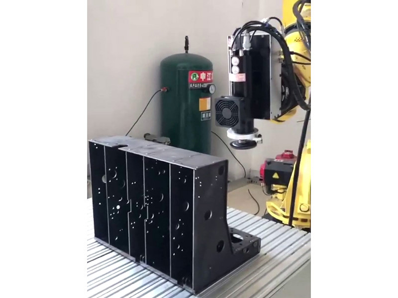
4.1 Robot Welding Systems
6-axis articulated robots with repeat positioning accuracy of ±0.02 mm are integrated with laser vision seam tracking systems (sampling frequency 1 kHz) to realize adaptive welding of complex chassis components. The system dynamically adjusts welding parameters according to seam position and gap width, reducing defect rates to below 0.1%.
4.2 Digital Twin-Driven Welding Simulation
Pre-welding simulation using digital twin technology predicts temperature field distribution and thermal deformation of chassis components, optimizing welding sequences and fixture positions. This technology reduces the number of physical welding trials by 60% and shortens the production preparation cycle by 30%.
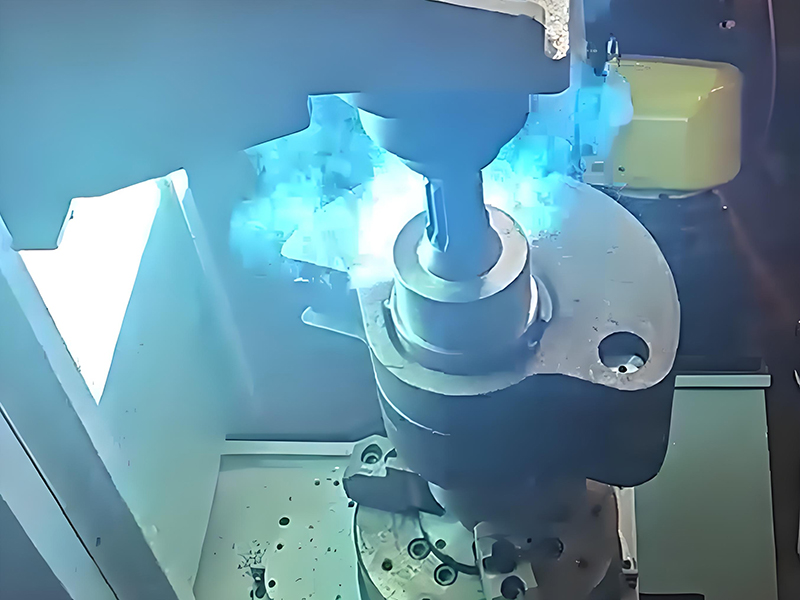
4.3 Real-Time Quality Monitoring
High-speed cameras and spectral sensors monitor molten pool morphology and plasma characteristics during welding. AI algorithms analyze real-time data to identify defect risks (e.g., burn-through, incomplete penetration) and adjust welding parameters in milliseconds, achieving closed-loop quality control.
5. Future Development Trends
5.1 Lightweight Material Welding Technology Upgrade
R&D of laser-ultrasonic hybrid welding and friction stir welding for magnesium alloy and carbon fiber reinforced polymer (CFRP) chassis components, further reducing vehicle weight.
5.2 Full-Automation and Unmanned Welding Workshops
Integration of
robot welding systems with automatic loading/unloading equipment and AGV logistics systems to realize 24/7 unmanned production of chassis components.
5.3 Green Welding Process Promotion
Adoption of low-fume flux-cored wires and energy-efficient inverter welding power supplies, reducing welding energy consumption by 25% and fume emissions by 40%.