3D Laser Welding Systems
Release time:2026-02-06
Visits:436
1. System Core Components and Configuration
A high-performance
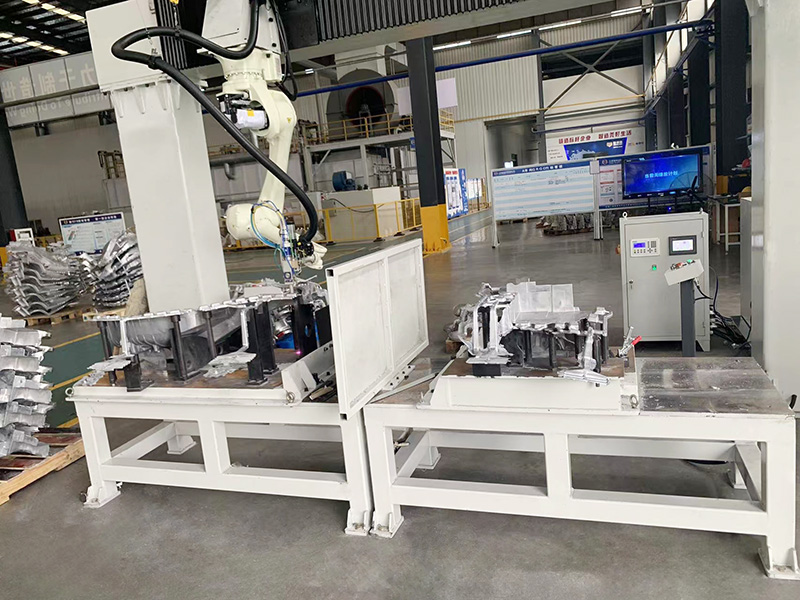
3D laser welding system is composed of four interconnected subsystems, each critical for achieving precision joining of complex components:
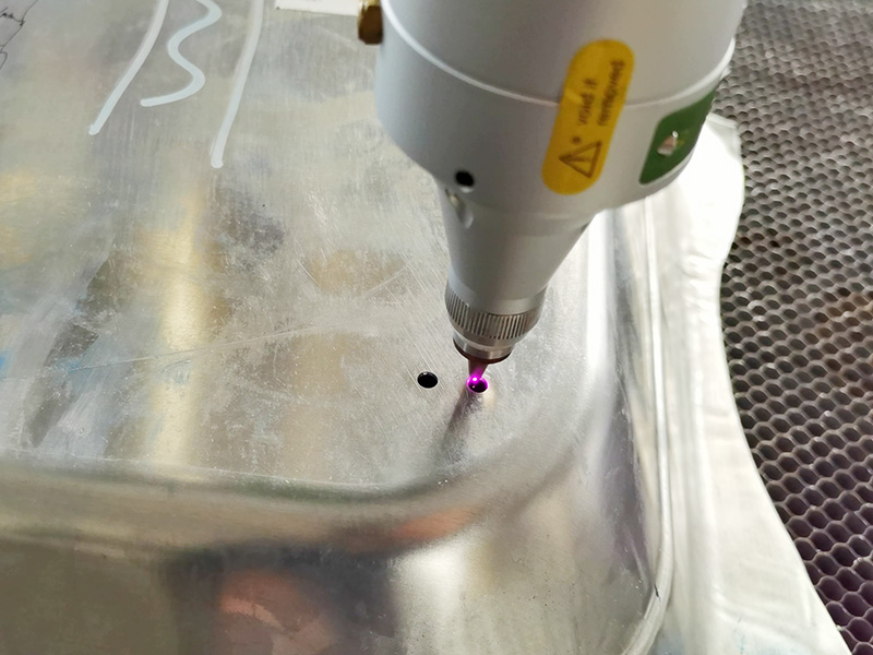
- Laser Source Module: Fiber lasers (1–15 kW) and disk lasers are the dominant light sources, characterized by high beam quality (low beam parameter product, BPP < 6 mm·mrad), stable energy output, and rapid response to power modulation. For high-reflectivity materials such as aluminum alloys and copper, green lasers (532 nm wavelength) or blue lasers (450 nm wavelength) are preferred to reduce energy loss caused by surface reflection and avoid plasma shielding effects.
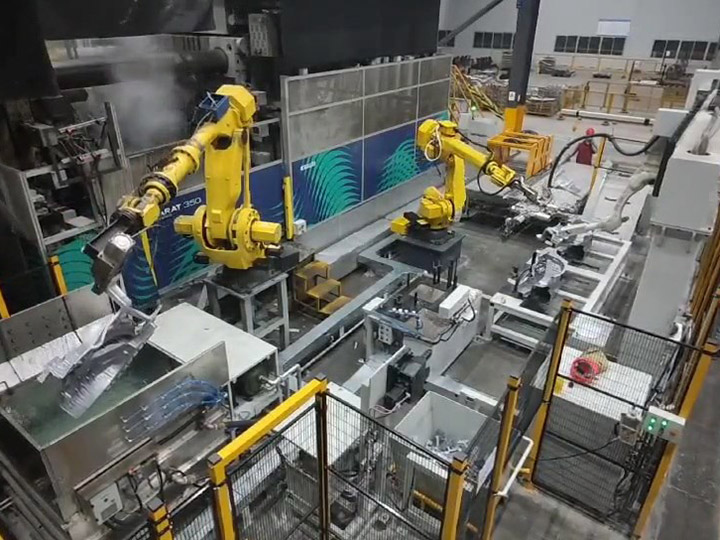
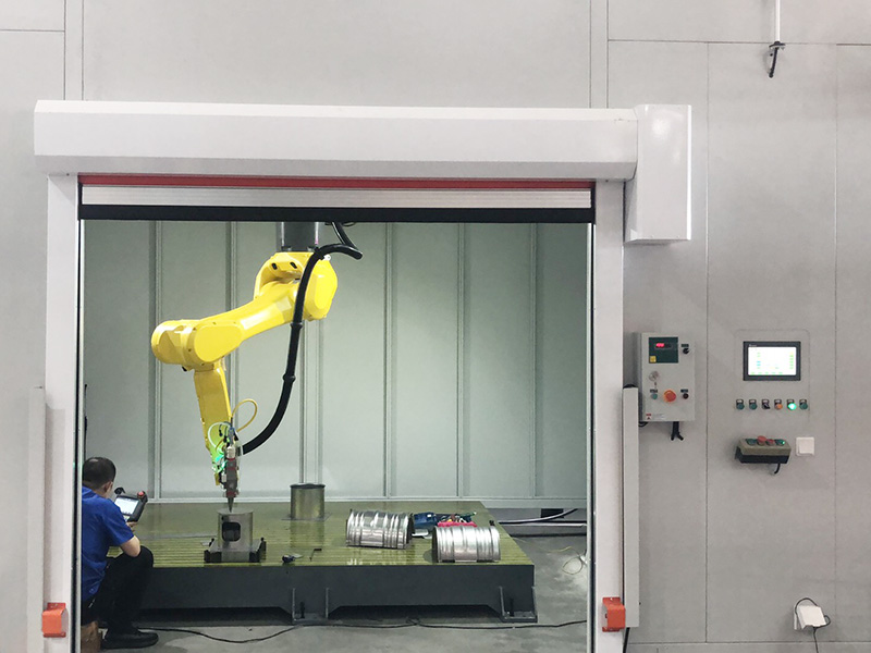
- 3D Motion Execution Unit: Integrated with a multi-axis CNC robotic arm (6–8 axes) or a gantry-type motion platform, the unit achieves high-precision positioning and trajectory following with a repeat positioning accuracy of ±0.02 mm. The robotic arm is equipped with a flexible wrist joint, enabling welding of complex spatial weld seams (e.g., curved surfaces, intersecting lines, and narrow cavity structures) that are inaccessible to traditional 2D welding equipment.
- Real-time Seam Tracking System: Equipped with a vision sensor (structured light or laser triangulation) and an adaptive control algorithm, the system captures weld seam position, gap width, and misalignment data in real time at a sampling frequency of up to 1 kHz. It dynamically adjusts the laser focus position and welding path to compensate for workpiece clamping errors and thermal deformation, ensuring consistent weld penetration depth.
- Shielding Gas and Process Control Module: Delivers shielding gas (argon, helium, or mixed gas) through a coaxial nozzle to isolate the molten pool from air, preventing oxidation and porosity. The module also integrates a process monitoring system (plasma spectroscopy, high-speed camera) to detect defects such as undercut, burn-through, and porosity during welding, and triggers adaptive adjustments (power reduction, speed adjustment) in milliseconds.
2. Key Technical Advantages
- High Flexibility for Complex Workpieces: Unlike traditional resistance welding or arc welding that relies on custom fixtures for specific components, 3D laser welding systems can weld components with irregular 3D geometries by programming motion trajectories, eliminating the need for fixture redesign and reducing production preparation time by 30–50%.
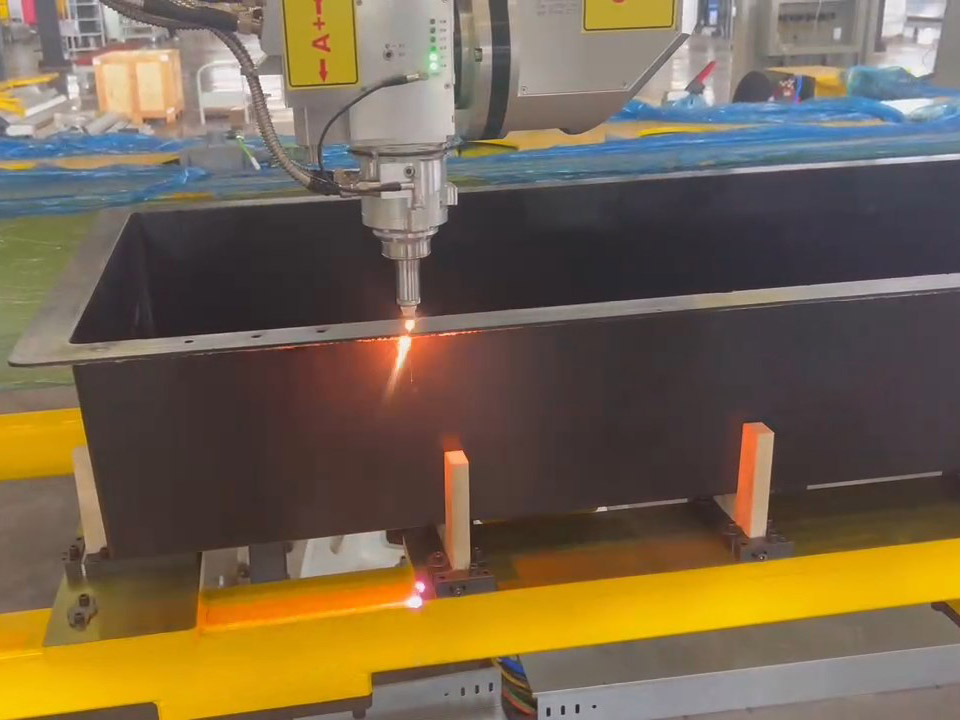
- Minimal Thermal Input and Deformation: The laser beam features a small spot diameter (0.1–0.5 mm) and high energy density (10⁶–10⁸ W/cm²), enabling rapid localized melting and solidification of the weld zone. The heat-affected zone (HAZ) is reduced to less than 0.3 mm, minimizing thermal deformation of thin-walled components (thickness < 1 mm) and eliminating the need for post-weld correction processes.
- High Welding Efficiency and Consistency: The system supports continuous welding speeds of 2–10 m/min, which is 3–5 times higher than that of TIG welding. The CNC-controlled motion and real-time seam tracking ensure uniform weld width and penetration depth across the entire weld seam, with defect rates reduced to less than 0.1% for mass production.
- Wide Compatibility with Materials and Thicknesses: It can join both similar metals (steel-steel, aluminum-aluminum) and dissimilar metals (steel-aluminum, copper-aluminum) with a workpiece thickness range of 0.1–12 mm. For thick plate welding, multi-pass overlapping welding or oscillating laser welding technology is adopted to improve weld fusion and reduce internal defects.
3. Critical Process Control Parameters
- Laser Power and Welding Speed Matching: For thin-walled stainless steel components (0.5 mm thickness), a laser power of 500–800 W and a welding speed of 4–6 m/min are recommended to avoid burn-through; for thick carbon steel plates (8 mm thickness), a 6 kW laser with a speed of 0.8–1.2 m/min and multi-pass welding is required to achieve full penetration.
- Focus Position Adjustment: The optimal focus position is typically 0–0.5 mm below the workpiece surface. A focus position that is too high reduces energy density and causes insufficient penetration, while a position that is too low leads to excessive energy concentration and weld undercut.
- Shielding Gas Parameters: Argon (purity ≥99.99%) is used for most steel and aluminum alloys, with a flow rate of 10–20 L/min; helium is preferred for high-temperature alloys to enhance heat transfer and improve weld surface quality. The nozzle-to-workpiece distance is controlled at 1–3 mm to ensure effective gas coverage.
4. Typical Industrial Applications
- Automotive Manufacturing: Welding of body-in-white components (door hinges, roof rails, battery trays for new energy vehicles), where the system’s high flexibility and low deformation meet the lightweight design requirements of automotive structures.
- Aerospace Industry: Joining of precision components such as aircraft engine turbine blades, rocket fuel tank pipelines, and satellite structural frames, with strict control over weld strength and fatigue resistance.
- Medical Device Production: Welding of stainless steel surgical instruments, titanium alloy implant components, and medical catheter assemblies, where minimal thermal deformation and high weld precision ensure compliance with medical biocompatibility standards.
- Consumer Electronics: Welding of 5G communication device housings, lithium battery tabs, and camera module brackets, supporting high-speed mass production of small, complex components.