1. Core Technical Components of Automatic Welding Machines
1.1 Intelligent Welding Power Supply System
The welding power supply serves as the energy core of automatic welding machines, adopting inverter technology and digital control algorithms to achieve precise regulation of welding current, voltage, and waveform. Key technical features include:
- Inverter control: Converts 50/60 Hz alternating current into high-frequency alternating current (10–100 kHz) through IGBT or MOSFET modules, with electro-optical conversion efficiency exceeding 85%—30% higher than traditional thyristor power supplies. It enables rapid response to dynamic load changes, with current adjustment response time less than 1 ms.
- Waveform customization: Supports multi-waveform output (constant current, constant voltage, pulsed DC, AC square wave) to adapt to different welding processes. For example, pulsed MIG welding waveforms reduce heat input for thin-walled aluminum alloy components, while high-frequency square wave waveforms enhance oxide film cleaning during aluminum TIG welding.
- Energy management: Integrates load monitoring and energy feedback functions, automatically adjusting power output according to weld seam position and material thickness to minimize energy consumption and thermal deformation.
1.2 High-precision Motion Control Unit
The motion control unit drives the welding torch or workpiece to move along preset trajectories, ensuring consistent weld seam tracking and positioning accuracy. Its core components and technical parameters include:
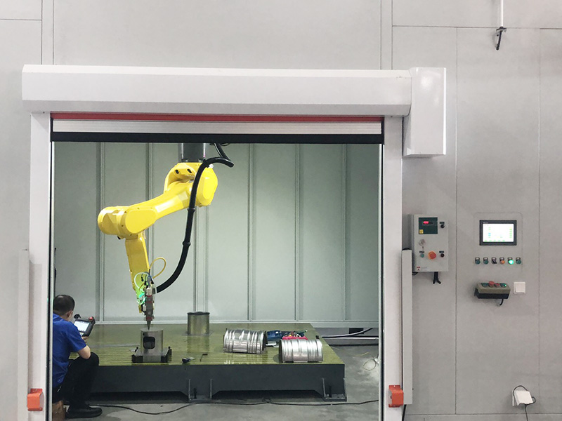
- Multi-axis linkage system: Equipped with 2–8 axis servo motors and precision ball screw drives, achieving repeat positioning accuracy of ±0.02–0.05 mm. Gantry-type motion units are suitable for large workpiece welding (e.g., ship hull plates, wind turbine towers), while articulated robotic arms are ideal for complex 3D weld seam welding (e.g., automotive chassis nodes).
- Trajectory planning algorithm: Adopts offline programming (OLP) and real-time interpolation technologies to optimize motion paths, avoiding abrupt acceleration/deceleration that causes weld bead discontinuity. For long straight weld seams, the constant speed control function maintains welding speed fluctuation within ±2%, ensuring uniform penetration depth.
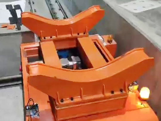
- Fixture integration: Customized fixtures with pneumatic or hydraulic clamping mechanisms fix workpieces stably, reducing positional deviation caused by thermal expansion and contraction. Fixture design follows the principle of minimal restraint to mitigate welding residual stress.
1.3 Sensing and Closed-loop Control Module
This module realizes real-time monitoring and adaptive adjustment of the welding process, which is the key to ensuring stable welding quality. Core sensing technologies include:
- Vision-based seam tracking: Uses 2D/3D laser vision sensors or CCD cameras to capture weld seam position, gap width, and misalignment data at a sampling frequency of 500 Hz–1 kHz. The system dynamically corrects the welding torch position with a response time of less than 10 ms, compensating for workpiece clamping errors and thermal deformation.
- Molten pool monitoring: Employs high-speed cameras and spectral analysis technology to monitor molten pool temperature, morphology, and size in real time. When detecting defects such as burn-through or incomplete fusion, the control system automatically adjusts welding current, speed, or shielding gas flow rate to eliminate defects.
- Arc sensor technology: Extracts arc voltage/current signals to calculate the distance between the welding torch and the workpiece surface, realizing real-time adjustment of torch height. It is widely used in arc welding processes (MIG/MAG, TIG) and has strong anti-interference ability in harsh industrial environments.
1.4 Auxiliary Function System
- Shielding gas delivery system: Precisely controls the flow rate and pressure of shielding gases (argon, CO₂, argon-CO₂ mixture) through mass flow controllers, with flow rate adjustment accuracy of ±0.1 L/min. Coaxial gas nozzles ensure uniform coverage of the molten pool, preventing oxidation and porosity.
- Wire feeding system: Adopts dual-drive wire feeders with stable wire feeding speed (0.5–30 m/min) to ensure consistent filler metal supply. For high-strength steel welding, the system supports multi-layer multi-pass welding with automatic wire feeding speed adjustment between layers.
- Fume extraction system: Integrates high-efficiency fume extractors and suction nozzles to collect welding fumes and dust, meeting industrial environmental protection standards (e.g., OSHA, GB 16297).
2. Key Technical Advantages of Automatic Welding Machines
2.1 High Welding Consistency and Quality Stability
Automated processes eliminate human errors caused by manual operation, ensuring uniform weld bead geometry, penetration depth, and mechanical properties. The defect rate of welds produced by automatic welding machines is typically below 0.2%, far lower than the 3–5% defect rate of manual welding. Weld joints meet strict industry standards such as AWS D1.1, ISO 15614, and GB 50661.
2.2 Significantly Improved Production Efficiency
Automatic welding machines achieve continuous welding without interruption, with welding speeds 2–5 times faster than manual welding. For example, automatic MIG welding of 10 mm thick carbon steel plates can reach a speed of 0.8–1.2 m/min, while manual welding only achieves 0.2–0.3 m/min. Integrated automatic loading/unloading systems further reduce non-welding time, improving overall equipment efficiency (OEE) to over 80%.
2.3 Strong Adaptability to Diverse Workpieces and Processes
By switching welding torches, adjusting process parameters, and replacing fixtures, a single automatic welding machine can handle welding tasks of different materials (carbon steel, stainless steel, aluminum alloy, copper alloy) and workpiece sizes (micro-components to large structural parts). It supports multiple welding processes including MIG/MAG, TIG, SAW, and laser welding, meeting the needs of multi-variety and small-batch production.
2.4 Reduced Labor Costs and Operational Risks
Automatic welding machines can operate continuously for 24 hours, reducing the demand for skilled welders and lowering labor costs by 40–60%. The closed-loop control system and safety protection devices (light barriers, emergency stop buttons) eliminate potential safety hazards such as arc radiation and splatter, ensuring operator safety.
3. Main Types of Automatic Welding Machines and Typical Applications
- Working principle: Uses resistance heat generated by current passing through the contact surface of workpieces to melt the metal and form weld joints, including spot welding, seam welding, and projection welding machines.
- Technical parameters: Welding current ranges from 1000–50,000 A, with welding time control accuracy of ±1 ms.
- Industry applications: Dominant in automotive manufacturing for welding body-in-white components (door panels, roof rails, trunk lids), with production lines achieving 1000+ weld spots per minute. Also used in home appliance manufacturing for welding refrigerator cabinets and washing machine inner tubs.
3.2 Arc Automatic Welding Machines
3.2.1 Automatic MIG/MAG Welding Machines
- Technical features: High deposition rate (5–20 kg/h), suitable for welding thick plates and long weld seams. Supports pulsed MIG welding for low-heat-input applications.
- Industry applications: Widely used in construction machinery (excavator boom, loader frame), shipbuilding (hull plate butt welding), and pressure vessel manufacturing (cylindrical shell welding).
3.2.2 Automatic TIG Welding Machines
- Technical features: High welding precision, narrow heat-affected zone (HAZ), suitable for welding thin-walled components and high-quality weld joints.
- Industry applications: Aerospace (aircraft engine pipeline welding), medical devices (stainless steel surgical instrument welding), and precision instrument manufacturing (sensor housing welding).
3.2.3 Automatic Submerged Arc Welding (SAW) Machines
- Technical features: High deposition rate (10–40 kg/h), deep penetration, suitable for thick plate welding (≥8 mm).
- Industry applications: Heavy steel structure manufacturing (steel bridge trusses, crane beams), oil and gas pipeline welding, and nuclear power plant pressure vessel manufacturing.
3.3 Laser Automatic Welding Machines
- Technical features: High energy density (10⁶–10⁸ W/cm²), minimal thermal deformation, suitable for precision welding of micro-components and dissimilar metals.
- Industry applications: New energy vehicles (battery tab welding, motor stator winding welding), consumer electronics (smartphone camera module welding, 5G base station component welding), and aerospace (satellite structural frame welding).
4. Core Application Guidelines and Precautions
4.1 Workpiece Preprocessing Requirements
Clean the weld zone (20–50 mm on both sides of the weld seam) to remove oil, rust, oxide films, and paint using methods such as grinding, sandblasting, ultrasonic cleaning, or chemical pickling. Contaminants on the workpiece surface will cause weld porosity, incomplete fusion, and reduced joint strength.
4.2 Process Parameter Matching Principles
Match welding parameters (current, voltage, speed, wire feeding speed) according to material type, thickness, and welding process. For example:
- Welding 3 mm thick stainless steel plates with automatic TIG welding: 120–150 A current, 12–15 V voltage, 0.3–0.5 m/min welding speed.
- Welding 10 mm thick carbon steel plates with automatic MIG welding: 250–300 A current, 28–32 V voltage, 0.8–1.0 m/min welding speed.
4.3 Equipment Calibration and Maintenance
- Regular calibration: Calibrate the motion control unit and seam tracking system every 1–3 months to ensure positioning accuracy. Verify the welding power supply output parameters using a welding parameter tester.
- Routine maintenance: Clean the welding torch nozzle and contact tip daily to prevent clogging; replace worn parts (nozzles, electrodes, wire feed rollers) in a timely manner; inspect the cooling system weekly to ensure the cooling water flow rate and temperature are within the normal range.
4.4 Quality Inspection Standards
Implement tiered quality inspection for welded workpieces:
- Visual inspection (VT): Check for surface defects such as cracks, porosity, undercut, and incomplete fusion.
- Non-destructive testing (NDT): Use ultrasonic testing (UT) for internal defects in thick plates, radiographic testing (RT) for critical weld joints, and magnetic particle testing (MT) for surface cracks in ferromagnetic materials.
- Mechanical property testing: Conduct tensile, impact, and bend tests on weld specimens to verify that the weld joint strength meets design requirements.