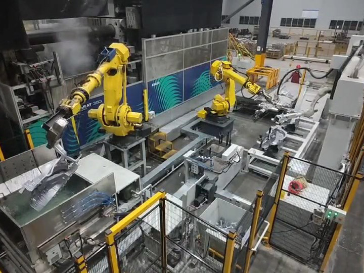
In the global energy sector, power transformers are critical infrastructure—responsible for transmitting and distributing electrical energy with minimal losses. Their manufacturing demands ultra-high precision, leak-tight welds, and compliance with stringent standards (e.g., IEC 60076, ANSI C57.12.00) to ensure decades of reliable operation. Against this backdrop, fully automatic welding lines have emerged as a transformative solution, replacing labor-intensive manual welding with integrated robotic, sensing, and control systems. This article explores the technical architecture, core components, application-specific benefits, and future trends of these lines, highlighting their role in elevating power transformer manufacturing efficiency, quality, and reliability.
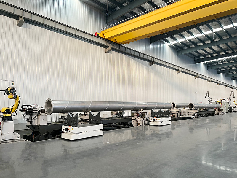
A fully automatic welding line for power transformers is a modular, closed-loop system designed to automate all critical welding processes in transformer fabrication—from core lamination assembly to tank seam welding. Unlike generic automated welding systems, it is engineered to address the unique challenges of transformer components: large dimensions (tanks up to 10+ meters), heavy gauge materials (steel up to 50 mm thickness), and strict leak-tightness requirements (≤ 1×10⁻⁶ mbar·L/s for oil-filled tanks).
The line operates on a sequential workflow integrated with upstream (material cutting, forming) and downstream (inspection, painting) processes, using PLC (Programmable Logic Controller) and MES (Manufacturing Execution System) software for real-time coordination. Key design principles include:
- Process Adaptability: Compatibility with multiple welding technologies (submerged arc welding, gas metal arc welding, laser welding) tailored to component type.
- Precision Control: Sub-millimeter positional accuracy to ensure weld alignment with transformer design tolerances (±0.5 mm for core joints).
- Quality Assurance: In-line monitoring (vision, ultrasonic testing) to detect defects during welding, eliminating post-production rework.
2. Core Components of a Fully Automatic Welding Line
The line’s functionality depends on five interdependent subsystems, each optimized for transformer-specific manufacturing tasks:
| Component Subsystem | Technical Specifications & Function |
|----------------------|-------------------------------------|
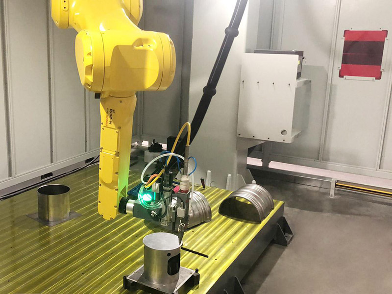
| Specialized Robotic Manipulators | - Gantry Robots: For large components (tanks, radiator panels) with linear axes (X/Y/Z) spanning 10–20 meters. Payload capacity: 50–200 kg (supports heavy submerged arc welding (SAW) torches).<br>- Articulated 6-Axis Robots: For precision tasks (core lamination welding, coil terminal connections). Positional accuracy: ±0.03 mm; repeatability: ±0.01 mm.<br>- Orbital Welding Units: For circular seams (e.g., transformer tank nozzles, bushing flanges) with 360° continuous weld capability. |
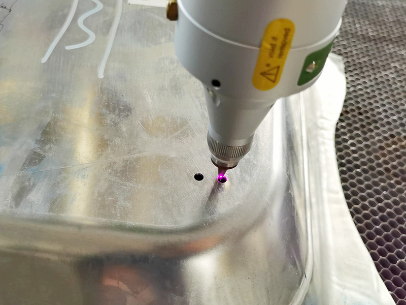
| Welding Technology Modules | Tailored to component material and geometry: <br>- Submerged Arc Welding (SAW): For thick steel tanks (15–50 mm) and radiator headers. Uses granular flux to protect the weld pool; deposition rate: 5–20 kg/h (ideal for high-volume, heavy-gauge welding).<br>- Gas Metal Arc Welding (GMAW/MIG): For medium-thickness components (5–15 mm) like core clamping structures. Shielding gas: 80%Ar/20%CO₂; current range: 200–500 A.<br>- Laser Welding (Fiber Laser): For precision joints (e.g., coil conductor connections, thin-gauge core laminations). Beam quality (M² < 1.2); spot size: 0.3–1 mm (minimizes heat distortion). |
| Real-Time Sensing & Monitoring Systems | - Laser Seam Trackers: Mounted on robot torches to detect weld joint position and adjust torch path in real time (compensates for ±2 mm part misalignment).<br>- Ultrasonic Testing (UT) Probes: In-line inspection of weld integrity (detects porosity, lack of fusion) with data logged to MES for compliance.<br>- Thermal Imaging Cameras: Monitor weld pool temperature (critical for SAW) to prevent overheating and ensure consistent microstructure.<br>- Leak Detection Sensors: Post-weld helium mass spectrometry for tank seams to verify leak-tightness (meets IEC 60076-1 standards). |
| Material Handling & Conveyor Systems | - Heavy-Duty Roller Conveyors: Transport transformer tanks (up to 50 tons) between welding stations; synchronized with robot cycles to avoid bottlenecks.<br>- Robotic Palletizers: Automate loading/unloading of core laminations (0.3–0.5 mm thickness) onto welding fixtures, reducing material damage.<br>- Modular Fixtures: Quick-change clamps (hydraulic or magnetic) for different transformer sizes (e.g., 10 MVA to 500 MVA); include alignment pins for sub-millimeter positioning. |
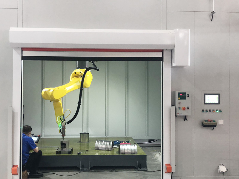
| Control & Integration Software | - PLC Control: Centralizes robot motion, welding parameters, and conveyor operation; supports IEC 61131-3 programming for custom workflows.<br>- MES Integration: Logs process data (weld current, voltage, travel speed) for traceability (critical for utility customers requiring full manufacturing records).<br>- CAD/CAM Import: Converts transformer 3D models (SolidWorks, AutoCAD) into optimized weld paths, eliminating manual programming.<br>- Remote Monitoring: Cloud-based dashboards for real-time line performance (OEE—Overall Equipment Efficiency, defect rates) and predictive maintenance alerts. |
3. Application-Specific Welding Processes for Power Transformers
Fully automatic lines are tailored to the three most critical transformer components—cores, tanks, and coils—each requiring distinct welding approaches to meet performance standards:
3.1 Transformer Core Welding
The core (composed of stacked electrical steel laminations) is the heart of the transformer, responsible for magnetic flux transfer. Welding must minimize eddy current losses and avoid lamination damage:
- Process: Laser welding (1–3 kW fiber lasers) or micro-GMAW for lamination bonding. Welds are limited to 1–2 mm in length to prevent magnetic short-circuits between laminations.
- Automation Benefit: Robotic articulators with 3D vision precisely align welds with lamination notches, reducing eddy current losses by 5–10% compared to manual welding (which often causes lamination misalignment).
- Quality Check: Post-weld magnetic flux testing (per IEC 60404-3) to verify core performance.
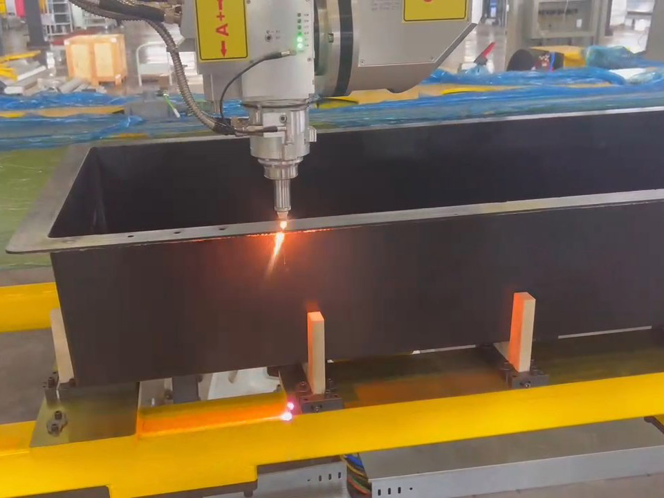
3.2 Transformer Tank Welding
The tank (mild steel or stainless steel) houses the core-coil assembly and insulating oil; leak-tightness and structural integrity are non-negotiable:
- Process: SAW for longitudinal/ circumferential tank seams (15–50 mm thickness) and GMAW for nozzle/flange connections. SAW flux is recycled via closed-loop systems to reduce waste.
- Automation Benefit: Gantry robots maintain consistent weld penetration (critical for 50 mm steel) and travel speed (0.5–1 m/min), eliminating manual SAW’s variability (which often causes undercutting or incomplete fusion). Leak defect rates drop from 8–12% (manual) to <0.5% (automatic).
- Compliance: Helium leak testing integrated into the line ensures tanks meet IEC 60076-5 standards for oil-filled transformers.
3.3 Transformer Coil Welding
Coils (wound copper or aluminum conductors) require low-resistance welds to minimize load losses and avoid overheating:
- Process: Laser welding (500 W–2 kW) for conductor splices (copper conductors up to 10 mm thickness) or resistance spot welding for coil end connections.
- Automation Benefit: Robotic orbital welders ensure concentric, uniform splices with resistance < 10 μΩ (meets ANSI C57.12.90 standards). Manual welding often introduces irregularities that increase load losses by 3–5%.
- Precision Control: Thermal cameras monitor weld temperature to prevent copper oxidation (which degrades conductivity); cooling systems (water or air) maintain conductor temperature < 150°C during welding.
4. Quantifiable Benefits of Fully Automatic Welding Lines
Compared to manual welding, fully automatic lines deliver transformative improvements in efficiency, quality, cost, and safety—directly addressing the pain points of transformer manufacturing:
| Benefit Category | Technical Rationale | Industrial Impact |
|-------------------|---------------------|--------------------|
| Efficiency & Throughput | - 24/7 continuous operation (OEE > 85% vs. 50–60% for manual lines).<br>- Parallel processing (e.g., tank welding and core assembly occurring simultaneously).<br>- Reduced setup time (modular fixtures and CAD/CAM import cut changeover from 8 hours to 1 hour for different transformer sizes). | - Production capacity increases by 100–150% (e.g., 200 transformers/year vs. 80–100 manually).<br>- Lead time for large transformers (500 MVA) reduced from 12 weeks to 6–8 weeks. |
| Weld Quality & Reliability | - Closed-loop parameter control (±1% variability in current/voltage vs. ±10–15% manually).<br>- In-line UT and leak detection eliminate post-production rework.<br>- Consistent microstructure (critical for tank steel fatigue resistance) via thermal monitoring. | - Weld defect rates drop from 10–15% (manual) to <1%—saving $50,000–$200,000/year in rework costs (e.g., tank repair or core replacement).<br>- Transformer lifespan extended by 10–15 years (from 25–30 years to 35–45 years) due to improved weld integrity. |
| Cost Optimization | - Labor savings: 1 operator supervises 4–6 welding stations vs. 1 welder per manual station (reduces labor costs by 60–70%).<br>- Material savings: SAW flux recycling (reduces flux waste by 80%) and laser welding’s minimal filler wire use (cuts wire consumption by 30%).<br>- Energy efficiency: Inverter-based welding power supplies use 15–20% less energy than traditional transformers. | - Total cost of ownership (TCO) reduced by 25–35% over 5 years. ROI achieved in 18–24 months for medium-volume lines (100+ transformers/year). |
| Safety & Compliance | - Human operators are removed from hazardous zones (SAW fumes, high-temperature tanks), reducing arc burn and respiratory risk by 95%.<br>- Automated data logging (weld parameters, inspection results) ensures compliance with IEC/ANSI standards and utility customer requirements (e.g., ISO 9001 traceability). | - Workplace safety incidents (welding-related) reduced to near-zero.<br>- Audit preparation time cut by 70% (MES stores all process data electronically). |
5. Implementation Considerations for Manufacturers
To maximize the value of fully automatic welding lines, transformer manufacturers must address three critical factors:
5.1 Line Sizing & Customization
- Transformer Capacity Range: Lines for small transformers (≤ 10 MVA) require compact articulated robots; lines for large power transformers (≥ 200 MVA) need heavy-duty gantry systems and 50+ ton material handling.
- Material Compatibility: Ensure welding modules support the manufacturer’s core materials (e.g., laser welding for high-silicon electrical steel, SAW for ASTM A36 tank steel).
- Future Scalability: Design lines with modular stations (e.g., add an extra orbital welding unit) to accommodate growing demand.
5.2 Operator Training & Maintenance
- Technical Training: Train operators in PLC programming, robot calibration, and in-line inspection (e.g., UT probe interpretation). Partner with robot vendors (KUKA, ABB) for certified training programs.
- Preventive Maintenance: Schedule weekly tasks (e.g., SAW flux hopper cleaning, laser lens calibration) and use IoT sensors to monitor robot joint wear (predictive maintenance reduces downtime by 30%).
- Spare Parts Inventory: Stock critical components (SAW torches, laser diodes) to minimize line downtime (target: <2 hours of unplanned downtime/month).
5.3 Compliance & Quality Assurance
- Standard Alignment: Configure software to enforce IEC/ANSI parameters (e.g., SAW travel speed for tank steel per IEC 60076-2).
- Data Integrity: Ensure MES software meets FDA 21 CFR Part 11 (electronic records) for traceability, critical for utility customers in regulated markets (e.g., North America, EU).
6. Future Trends: Advancing Fully Automatic Welding Lines
As the power transformer industry evolves (e.g., shift to renewable energy, smart grids), fully automatic welding lines will integrate three key innovations:
6.1 AI-Driven Process Optimization
Machine learning algorithms will analyze historical weld data (10,000+ welds) to:
- Auto-adjust parameters (e.g., SAW flux feed rate) for new materials (e.g., high-strength low-alloy (HSLA) steel for lightweight tanks).
- Predict defects (e.g., porosity in coil welds) before they occur, reducing scrap rates by 40%.
6.2 Digital Twin Integration
Virtual replicas of the welding line will simulate:
- New transformer designs (e.g., 3D-printed core components) to optimize weld paths without physical prototyping.
- Line bottlenecks (e.g., conveyor speed mismatched to robot cycles) to improve OEE by 10–15%.
6.3 Green Welding Technologies
- Low-Flux SAW Systems: Reduce flux consumption by 50% using recycled, eco-friendly flux (complies with EU REACH regulations).
- Energy-Recovery Welding Power Supplies: Capture and reuse excess energy from welding arcs, cutting line energy use by 20%.