In modern manufacturing, where operational efficiency, quality consistency, and cost optimization define market competitiveness, arc robotic welding has emerged as a transformative solution. Unlike manual arc welding—reliant on operator skill, prone to fatigue, and limited by human throughput—arc robotic welding systems integrate programmable robotics, precision arc welding technology, and real-time process control to streamline joining operations. This article examines the technical foundations of arc robotic welding, its quantifiable efficiency gains, industrial applications, implementation considerations, and future trends, providing a comprehensive framework for understanding its impact on manufacturing productivity.
1. Technical Fundamentals of Arc Robotic Welding Systems
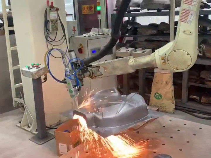
Arc robotic welding systems automate gas metal arc welding (GMAW/MIG), gas tungsten arc welding (GTAW/TIG), flux-cored arc welding (FCAW), or shielded metal arc welding (SMAW) processes using programmable robotic arms. Their design prioritizes motion precision, process stability, and integration flexibility—core attributes that drive efficiency.
1.1 Core System Components
Each component works in synergy to ensure consistent, high-speed welding:
| Component | Function & Technical Specifications |
|-----------|-------------------------------------|
| 6-Axis Robotic Manipulator | The primary motion unit, typically with 6 degrees of freedom (DOF) for 3D weld path execution. Key specs: <br> - Positional accuracy: ±0.02–±0.05 mm <br> - Repeatability: ±0.01 mm <br> - Payload capacity: 5–150 kg (supports welding torches, wire feeders, and vision sensors) <br> - Maximum reach: 1.2–3.5 m (accommodates small components to large structures). |
| Arc Welding Module | Includes: <br> - Welding Torch: Optimized for GMAW/TIG/FCAW (e.g., water-cooled torches for high-amperage GMAW, 150–500 A). <br> - Wire Feeder: Synchronized with the robot controller to deliver filler wire (0.8–1.6 mm diameter) at 0.5–20 m/min. <br> - Shielding Gas Delivery: Regulated flow (10–30 L/min) of argon, CO₂, or argon-CO₂ mixtures to protect the weld pool from atmospheric contamination. |
| Power Source | Inverter-based arc power supplies (110–480 V) with: <br> - Constant voltage (CV) for GMAW/FCAW (maintains stable arc length). <br> - Constant current (CC) for GTAW/SMAW (controls heat input). <br> - Digital control for real-time adjustment of voltage (15–40 V) and current (50–500 A) to match material thickness (0.5–50 mm) and type. |
| Robot Controller | The "brain" of the system, featuring: <br> - CAD/CAM integration for importing 3D part models and generating weld paths (G-code). <br> - Process monitoring software (e.g., arc voltage sensing, weld current logging) to detect deviations (e.g., wire feed errors, torch misalignment). <br> - Safety interlocks (emergency stops, light curtains) to comply with ISO 10218-1 (robotic safety standards). |
| Peripheral Sensors | Optional but critical for efficiency: <br> - Seam Trackers: Laser or vision-based sensors (e.g., 2D cameras) that correct torch position in real time (±0.5 mm tolerance) to account for part misalignment. <br> - Weld Pool Monitors: High-speed cameras or pyrometers to track weld pool temperature and prevent defects (e.g., porosity, burn-through). |
1.2 Common Arc Robotic Welding Configurations
Systems are tailored to application needs, with three dominant types:
| Configuration | Key Characteristics | Ideal Applications |
|---------------|---------------------|--------------------|
| Articulated Robots | Rotary joints (6+ DOF) for maximum flexibility; compact footprint. | Complex 3D welds (e.g., automotive chassis, aerospace components). |
| Gantry Robots | Linear motion axes (X/Y/Z) mounted on overhead beams; large work envelope (up to 50 m). | Large-scale structures (e.g., construction steel beams, ship hulls). |
| SCARA Robots | Selective Compliance Assembly Robot Arm (4 DOF); high speed (up to 5 m/s) for planar motion. | High-volume, 2D welds (e.g., electronics enclosures, small automotive parts). |
2. Quantifiable Efficiency Enhancements of Arc Robotic
Welding
The efficiency gains of arc robotic welding are not theoretical—they are measurable across four critical manufacturing metrics: throughput, quality, labor utilization, and cost. These gains stem from the system’s ability to eliminate human limitations (fatigue, inconsistency) and optimize process parameters.
2.1 Throughput: Maximizing Production Volume
- Continuous Operation: Unlike human welders (limited to 6–8 hours of productive work/day, including breaks), arc robotic systems operate 24/7 with only 1–2 hours/week of preventive maintenance. This increases effective production time by 200–300%.
- High-Speed Welding: Robots maintain consistent travel speeds (0.5–3 m/min) for GMAW/FCAW—2–3x faster than skilled manual welders (0.2–1 m/min). For example, a robotic system can weld 100 automotive door frames/day, compared to 30–40 for a manual welder.
- Multi-Torch Integration: Some systems (e.g., gantry robots) support 2–4 synchronized torches, enabling parallel welding of multiple seams (e.g., dual-side welding of steel beams). This further boosts throughput by 50–100%.
2.2 Quality: Minimizing Defects and Rework
- Consistent Process Parameters: Robots execute preprogrammed voltage, current, and travel speed with ±1% variability—far below the ±10–15% variability of manual welding. This reduces weld defect rates from 5–10% (manual) to <1% (robotic).
- Narrow Heat-Affected Zone (HAZ): Precise heat input control prevents material warpage (critical for thin-walled components, e.g., automotive exhausts) and reduces post-weld straightening—saving 1–2 hours of rework per part.
- In-Process Defect Detection: Seam trackers and weld pool monitors correct deviations in real time (e.g., adjusting torch position if a part is misaligned) and flag defects (e.g., lack of fusion) before they compromise the part. This eliminates scrap costs (average $50–$500/defective part for industrial components).
2.3 Labor Efficiency: Reducing Dependence on Skilled Welders
- Labor Cost Savings: A single operator can supervise 2–4 arc robotic systems (vs. 1 operator per manual station). For a manufacturing plant with 10 welding stations, this reduces labor requirements by 75%—translating to $100,000–$500,000/year in savings (based on $25–$50/hour for skilled welders).
- Skill Gap Mitigation: The global shortage of certified welders (e.g., 300,000+ unfilled positions in the U.S. alone) makes automation critical. Robots eliminate the need for highly skilled operators—trained technicians (1–2 weeks of training) can manage systems, reducing recruitment and training costs.
2.4 Cost Optimization: Lowering Total Cost of Ownership (TCO)
- Material Savings: Precise wire feed control reduces filler wire waste by 10–15% (manual welders often overuse wire to compensate for arc instability). For a plant using 10,000 kg of wire/year ($5/kg), this saves $5,000–$7,500/year.
- Energy Efficiency: Inverter-based power supplies use 15–20% less energy than traditional transformer-based units, cutting electricity costs by $1,000–$3,000/year per system.
- Long-Term ROI: While initial costs are high ($50,000–$300,000 per system), most manufacturers achieve ROI in 1–3 years due to throughput gains, labor savings, and defect reduction.
3. Industrial Applications of Arc Robotic Welding
Arc robotic welding is versatile across sectors, with each industry leveraging its efficiency gains to address unique challenges:
3.1 Automotive Manufacturing
The automotive industry was the first to adopt arc robotic welding (1960s) and remains its largest user, driven by high-volume production and quality standards:
- Body-in-White (BIW) Assembly: GMAW robotic systems weld high-strength steel (HSS) and aluminum alloy BIW components (e.g., door frames, roof rails) with 99.9% defect-free rates. For example, a single automotive plant uses 500+ articulated robots to produce 1,000+ vehicles/day.
- Powertrain Components: FCAW robots weld cast iron or aluminum engine blocks and transmission housings, ensuring hermetic seals to prevent fluid leaks.
- EV Battery Enclosures: GTAW robots weld aluminum battery casings (0.8–2 mm thickness) with minimal distortion—critical for protecting EV batteries from impact.
3.2 Aerospace & Defense
Aerospace demands ultra-high precision (±0.01 mm) and compliance with standards like AWS D17.1 (aerospace welding). Arc robotic systems deliver:
- Airframe Structures: GTAW robots weld titanium (Ti-6Al-4V) and nickel-based superalloys (Inconel 718) for wing spars and fuselage frames, with narrow HAZ to preserve material strength at high altitudes.
- Engine Components: GMAW robots weld turbine blades and combustion chambers, with in-process monitoring to detect micro-cracks (a critical safety risk).
- Military Vehicles: FCAW gantry robots weld armor steel plates (10–30 mm thickness) for tanks and armored personnel carriers, ensuring ballistic resistance.
3.3 Construction & Heavy Industry
For large-scale, heavy-gauge components, arc robotic welding solves efficiency and safety challenges:
- Structural Steel: Gantry robots weld I-beams, box girders, and trusses (steel thickness 10–50 mm) for bridges and high-rise buildings, reducing fabrication time by 50% compared to manual welding.
- Shipbuilding: Articulated robots weld hull plates (20–40 mm thickness) using FCAW, with seam trackers to compensate for plate misalignment (common in shipyards).
- Mining Equipment: Robotic systems weld thick-walled excavator buckets and conveyor frames (abrasion-resistant steel), extending component lifespan by 20–30% via consistent weld quality.
3.4 Electronics & Medical Devices
Even small-scale, precision-critical sectors benefit from compact arc robotic systems:
- Electronics Enclosures: SCARA robots use micro-GMAW to weld stainless steel or aluminum enclosures for smartphones and industrial sensors (weld seam width: 0.5–1 mm).
- Medical Instruments: GTAW robots weld titanium surgical tools (e.g., forceps, scalpels) with burr-free seams to avoid tissue irritation, complying with FDA 21 CFR Part 820.
4. Implementation Considerations for Arc Robotic Welding
To maximize efficiency gains, manufacturers must address three key factors during implementation:
4.1 Needs Assessment & System Selection
- Material & Weld Requirements: Match the system to material type (steel, aluminum, titanium) and weld process (GMAW for high volume, GTAW for precision). For example, aluminum welding requires water-cooled torches and AC power supplies.
- Production Volume: High-volume (10,000+ parts/year) operations benefit from articulated or gantry robots; low-volume (100–1,000 parts/year) job shops may opt for compact SCARA robots with quick-change fixturing.
- Work Envelope: Ensure the robot’s reach covers the largest part dimensions (e.g., a 3.5 m reach gantry robot for 10 m steel beams).
4.2 Integration & Training
- Production Line Integration: Align robot cycles with upstream/downstream processes (e.g., part loading/unloading conveyors) to avoid bottlenecks. Use PLC (Programmable Logic Controller) integration to sync robot operation with other machines.
- Operator Training: Train technicians in: <br> 1. Robot programming (teach pendant and CAD/CAM software). <br> 2. Maintenance (torch cleaning, wire feeder calibration). <br> 3. Troubleshooting (e.g., arc instability, sensor errors). <br> Certification programs (e.g., AWS Robotic Arc Welding Certification) ensure competency.
4.3 Addressing Implementation Challenges
| Challenge | Mitigation Strategy |
|-----------|-------------------|
| High Initial Cost | Use leasing or equipment-as-a-service (EaaS) models to spread costs; prioritize high-value applications (e.g., EV battery welding) for faster ROI. |
| Downtime from Malfunctions | Implement predictive maintenance (e.g., vibration sensors on robot joints, power supply health monitoring) to schedule repairs before failures; stock critical spare parts (torches, wire feeders). |
| Part Tolerance Variability | Integrate laser seam trackers or 3D vision systems to adjust for part misalignment (±0.5 mm tolerance); use modular fixturing to stabilize irregular parts. |
5. Future Trends: Enhancing Efficiency Further
Arc robotic welding will become even more efficient with three emerging technologies:
- AI-Powered Process Optimization: Machine learning algorithms will analyze historical weld data to auto-adjust parameters (voltage, speed) for new materials, reducing setup time by 80%.
- Digital Twins: Virtual replicas of welding cells will simulate weld paths and predict defects (e.g., porosity) before physical production, cutting trial-and-error costs by 50%.
- Collaborative Arc Robots (Cobots): Low-payload (5–10 kg) cobots with force-sensing technology will enable human-robot collaboration (e.g., operators load parts while cobots weld), expanding automation to small shops.