Chassis Welding: Methods, Quality Control And Automation
Release time:2026-09-28
Visits:2
Chassis welding is the joining of frames and load-bearing structures for trucks, trailers, buses, agricultural machines and construction equipment. The parts are long, the welds carry heavy service loads, and distortion is a constant fight. This article explains the welding methods used on chassis, how quality is controlled, and where automation pays off.
What Chassis Welding Covers
Chassis work includes side rails, cross members, brackets, suspension mounts, axle housings and cab frames. Materials are mostly carbon steel and high-strength low-alloy steel, with aluminum growing in trailers, buses and electric vehicles. Plate and tube thickness typically runs from 2 mm to 15 mm. The joints are mostly fillet welds, with some butt welds on rails and plug welds on closed sections.
Every weld on a chassis is a structural weld. A crack in a bracket weld can become a fatigue failure in service, which is why weld quality on chassis is treated with more care than on non-structural fabrication.
Main Welding Methods for Chassis
MIG/MAG welding. The default for steel chassis. Solid wire with CO2 or an argon-CO2 mix gives good penetration and speed. It handles the long fillet welds on rails and brackets well.
Flux-cored arc welding. Higher deposition for thicker sections, and more tolerant of drafts outdoors. Common in heavy truck and construction machinery frames.
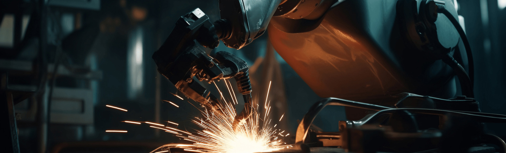
Robotic MIG welding. The standard for high-volume frames. Robots hold torch angle and speed constant, which fillet welds on long rails need.
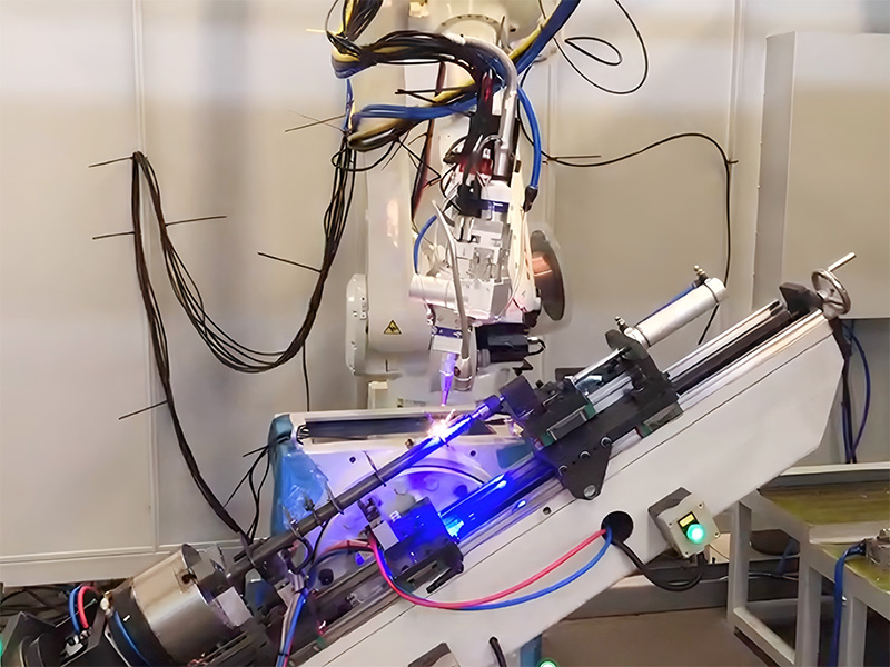
Laser welding. Used on aluminum chassis and battery trays in electric vehicles. Low heat input means less distortion, and the narrow weld suits thin sections.
Resistance spot welding. Used for body-in-white and cab assembly rather than frames, but worth noting because chassis shops often handle cabs too.
The Distortion Problem
Long, thin chassis members warp when heat input is uneven. A single long fillet on one side of a rail can bow the whole member. Control comes from several directions at once:
Rigid fixtures and clamps that hold the part against the heat.
Weld sequence planning: alternating sides, back-stepping, or welding both sides of a joint in turn so shrinkage cancels out.
Lower heat input processes, including pulsed MIG and laser, which put less energy into the part.
Compensation built into the fixture, such as pre-setting the part to the expected distortion.
Fixtures and Clamping
A
chassis welding fixture does three jobs: it locates the parts, holds them during welding, and prevents the weld shrinkage from pulling the assembly out of tolerance. Design points that matter: stable datum points that every fixture references, clamp force high enough to hold but not crush thin tube, copper or steel backing bars under critical welds to cool the pool, and quick-release clamps so cycle time does not disappear in loading and unloading.
On production lines, the fixture usually travels with the part from station to station, keeping the same datum through the whole welding sequence.
Automation of Chassis Welding
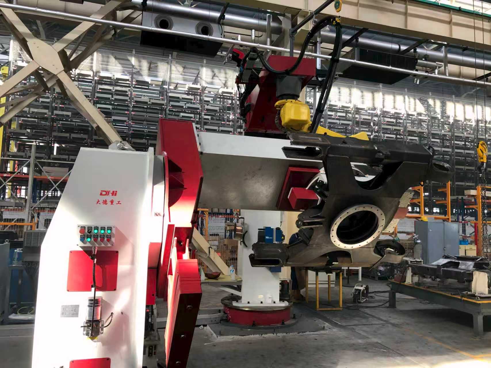
Robotic cells with positioners handle brackets and sub-assemblies. Dedicated chassis welding production lines take the full frame: fixtures on a transfer system, robots welding both sides, and positioners rotating the assembly for downhand welds. Laser cutting is often paired with welding, since accurately trimmed blanks make weld gaps consistent.
Automation pays for itself on chassis because the geometry repeats. A frame that is welded by hand varies with the welder; a frame that is welded by robots is the same every cycle, which also makes the dimensional checks predictable.
Quality Control
Fit-up checks come first. Gap, alignment and clamping are checked before the arc starts, because welding cannot fix a poorly fitted joint. During and after welding: visual inspection for cracks, undercut and porosity, dimensional measurement against the fixture or a CMM, and NDT on critical welds, usually magnetic particle testing for surface cracks and ultrasonic or radiographic testing where service loads are high.
Process qualification follows standards such as AWS D1.1 for steel structures, and welder or robot program qualification is documented per project. On fatigue-critical chassis, the weld toe quality and the absence of starts and stops at high-stress points are inspected deliberately.
Bottom Line
Chassis welding rewards discipline: rigid fixtures, controlled heat input, and a weld sequence that manages distortion before it happens. For repeat products, robotic welding turns that discipline into a standard that runs every shift. Dade Heavy Industry builds chassis welding production lines and robotic welding workstations, and also supplies laser cutting equipment for chassis blanks, so the cutting and welding steps can be matched to the same tolerances.