Vacuum Contactor For Welding Machine: Wiring, Ratings And Care
Release time:2026-10-23
Visits:1
A welding machine is more than a transformer and a torch. Between the incoming supply and the welding circuit sits a switching device that starts and stops the weld current, and in most production machines that device is a contactor. This article looks at the contactor's role inside a welding machine, how it is wired and controlled, and why vacuum contactors have become the preferred type.
Where the Contactor Sits in the Machine
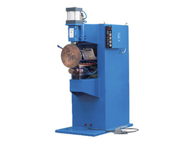
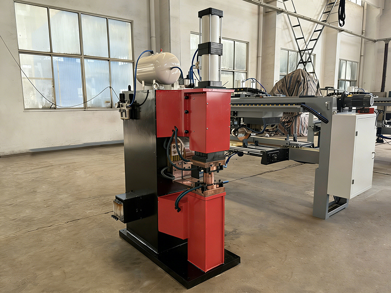
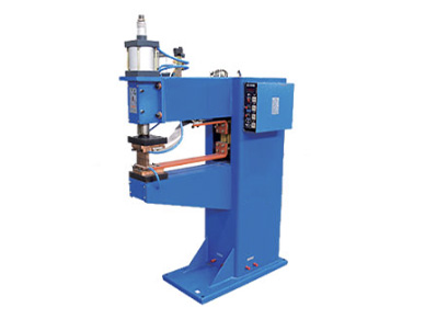
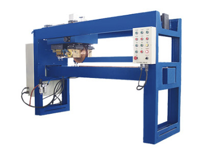
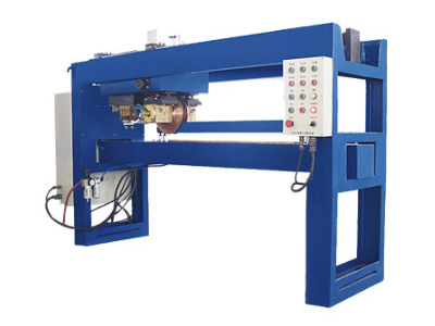
In an AC resistance welding machine, the contactor connects the supply to the primary winding of the welding transformer. Close the contactor and the transformer is energized; open it and the weld circuit goes dead. The welding controller times the weld precisely, but the contactor is the device that physically makes and breaks the power path.
In capacitor discharge (CD) welding machines, the contactor or a similar switching device controls charging of the capacitor bank and the discharge path. In some machines, the contactor works alongside thyristor stacks: the thyristors modulate the weld current, while the contactor provides the coarse on-off and isolates the circuit between welds. In all these roles, the switching device sees the same thing: frequent operation, inductive loads, and shop-floor abuse.
Why a Vacuum Contactor for a Welding Machine
The machine's control circuit may be clean, but the switching duty is not. Each weld cycle is a make-and-break operation on an inductive circuit. Open the contacts under load and an arc forms; the device has to extinguish it fast or the contacts erode. A vacuum contactor extinguishes the arc inside a sealed vacuum interrupter in a fraction of a cycle. The contacts stay clean, the mechanism stays light, and the unit keeps its ratings for millions of operations.
For a machine that welds all day, that means fewer failures, no contact dressing, and no arcing residue in the panel. It also means the machine holds its weld schedule, because a worn contactor can add resistance and heat that drift the weld current.
Wiring and Control Connections
A typical installation has three connections to get right: the power circuit, the coil circuit, and the auxiliary contacts.
Power circuit. The contactor's main poles carry the transformer primary current. Use cable sized for the continuous current and terminated tightly, because a loose connection runs hot and fails first.
Coil circuit. The coil is energized by the control voltage, typically 110 V, 220 V or 380 V AC, or 24 V DC in PLC-controlled machines. The welding controller or PLC switches the coil, often through a solid-state output or a small relay.
Auxiliary contacts. These report contactor state to the control: interlock signals, weld-permit signals, and fault indication. On vacuum contactors the auxiliary contacts are separate from the sealed main contacts, so their state always reflects the mechanism.
Coil Voltage and Control
Match the coil to the control system, not to the mains. If the machine uses 24 V DC controls, buy a 24 V DC coil. Wrong coil voltage is the most common installation error, and it shows up as a contactor that will not pull in, or one that hums and overheats. Check the pick-up and holding voltage range against the actual supply, especially on long cable runs where voltage drop matters.
Failure Signs to Watch
Chatter or buzzing. The coil or mechanism is not holding cleanly; check coil voltage and mechanical binding.
Failure to close. Coil circuit open, or the mechanism jammed.
Failure to open. Welded contacts or a stuck mechanism. With a vacuum unit this is rare, but the mechanism still needs its periodic inspection.
Overheating. Loose connections, oversized current, or a coil rated for the wrong voltage.
When a machine starts making inconsistent welds, check the switching device before blaming the transformer. Contact resistance that climbs with wear shows up as weld variability.
Maintenance Routine
Vacuum contactors need far less attention than air units, but they are not zero-maintenance. The routine is simple: check the mechanism for free movement, verify the coil pulls in and drops out at the right voltages, inspect the auxiliary contacts, and torque the power connections. Clean the enclosure vents so the mechanism does not run hot. On most machines, an annual check is enough.
Bottom Line
The contactor in a
welding machine takes the hardest duty in the panel. A vacuum contactor removes the two classic failure modes, contact erosion and arc damage, and turns switching maintenance into an annual check. When you replace a contactor in a welding machine, match the current rating to the transformer primary, match the coil to the control voltage, and check the auxiliary wiring once the unit is in. Dade Heavy Industry builds resistance welding machines and automated welding equipment, and specifies vacuum contactors for continuous-duty machines.