3D Curved Surface Laser Cutting Machine: Holding Focus On A Curved Part
Release time:2026-11-23
Visits:6
A curved surface breaks the assumptions that flat laser cutting is built on. On a flat sheet, the distance from the nozzle to the material is fixed by the table, the focus is set once, and the only variables are power, speed and gas. On a curved surface, the nozzle-to-work distance changes with every millimetre of travel unless the machine actively controls it, and the beam angle relative to the surface changes with it.
That is why a
3D curved surface laser cutting machine is judged by a different metric than a flat-bed machine. Not bed size, not acceleration, but how tightly it can hold focus and normality across a surface that is trying to move away from the head.
What Curvature Does to a Cut
Focus drift along the surface
Depth of focus at cutting powers is short. A 2 kW fiber source with a 150 mm focal length has a usable depth of focus in the region of 1 to 1.5 mm. On a part with a 300 mm radius, a 1° error in head orientation moves the focus point by about 5 mm along the surface — well outside that window. The result is a cut that starts clean and ends with dross, or a kerf that widens in one direction.
Angular error becomes positional error
On a flat plate, a 0.1° angular error at the wrist shifts the spot by 0.1 mm per metre of standoff — negligible. On a curved surface, the same angular error tilts the beam relative to the surface normal, which changes the effective kerf width and the taper. The cut can be dimensionally correct at the entry point and 0.15 mm off at the exit.
The Accuracy Budget
Published machine accuracy is one line in a long addition. A realistic budget for a curved trim on 1.5 mm hot-formed steel looks like this:
|
Contribution |
Typical value |
How it is controlled |
|
Machine positioning |
±0.03 to ±0.05 mm |
Kinematics and scale feedback |
|
TCP and calibration |
±0.05 mm |
Shift calibration, thermal compensation |
|
Path from CAD vs real part |
±0.3 to ±1.0 mm |
Probing, scanning, or tracking |
|
Fixture location |
±0.1 mm |
Datum stops, not clamps |
|
Thermal growth during shift |
±0.05 mm |
Warm-up cycle, compensation |
|
Total, realistic |
±0.4 to ±1.1 mm |
Dominated by part deviation |
The lesson is blunt: buying a machine with ±0.03 mm repeatability does not give you a ±0.03 mm part. It gives you the headroom to spend on part deviation. A machine with poor positioning accuracy has no way to recover that error, which is why the specification still matters even though it is not the largest term.
Kinematics for Curved Surfaces
Five-axis gantry
Two linear axes carry a cross beam, the head provides two rotary axes, and a third linear axis controls standoff. Stiffness is high, which keeps the focus stable through acceleration, and the working envelope suits panels up to several metres. The five-axis gantry is the reference configuration for hot-formed automotive parts, where the trim line runs around a hardened A-pillar or B-pillar and the edge must be dimensionally exact because it sets the gap to the next panel.
Automatic Small Circle Round Shape Robotic Cutting Machine
Dade Heavy Industry's
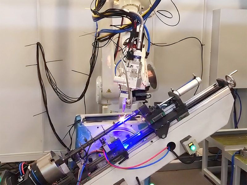
3D five-axis fiber laser cutting machine is built on this principle: five-axis motion control combined with fiber laser cutting for multi-angle, multi-directional processing of complex three-dimensional components, aimed at aerospace, automotive and mould work.
Robot with an external axis
A six-axis arm plus a rotary or linear positioner covers most parts under 2 m and costs less than a comparable gantry. The trade is stiffness: at full extension the arm deflects, so the programmer keeps the path inside the comfortable envelope and uses the positioner to bring the work to the robot rather than stretching the robot to the work.
When a rotary table is the cheapest axis
For parts that are bodies of revolution — motor housings, tube ends, cylindrical shells — a rotary table under a fixed head gives you the curved path for the price of one servo. A two-axis positioner plus a three-axis head often outperforms a five-axis gantry on these parts, because the part's own geometry supplies the curvature.
Programming a Surface Path
Offset from the surface, not from the edge
Two different offsets matter: the trim line offset in the surface plane, which sets the part dimension, and the standoff offset normal to the surface, which sets focus. Programming tools handle them separately, and the second is the one that gets forgotten during a manual teach. On a curved part, teach-by-doing produces a path that is only correct at the points that were taught.
Simulating collisions
Curved parts have deep pockets, upstands and flanges. Run a full kinematic simulation with the real head model, including the cable dress, before the first cut. Collisions in 3D cutting usually happen on the retract move, not on the cut.
Fixture and Support on Curved Geometry
A curved part supported at four points will flex between them. Support it on a machined nest that matches the inner surface, or on a vacuum fixture with cups placed along the trim line rather than at the centre. Where the part is thin and the trim runs close to an edge, add a sacrificial backing so the cut edge does not vibrate.
Clamping force deserves attention. Over-clamping a curved panel flattens it locally, the cut is made in the flattened state, and the part springs back to a shape whose trim line is now wrong. Clamp to locate, not to straighten.
Cutting Hot-Formed and Coated Surfaces
Hot-formed steel arrives with an Al-Si coating and a hardness that reaches 1,500 HV. A 3 kW source cuts it cleanly at trim-line speeds of 3 to 6 m/min, but the coating produces a hard, abrasive dross that wears the nozzle and contaminates the kerf. Use a larger nozzle diameter, higher assist gas pressure, and a nozzle inspection interval measured in hours rather than shifts.
On aluminium castings, the reflective surface and the varying section thickness mean the process needs a power margin. Dade's chassis aluminium cutting system uses a Kawasaki RA20N with a Raycus 2 kW source on rear and longitudinal beam castings, cutting at high speed with stable quality — the 2 kW class being chosen for section thickness rather than for speed.
Alternatives on Curved Parts
|
Process |
Edge quality |
Speed |
Tooling |
Best for |
|
5-axis laser |
Good, minimal burr |
High |
Fixture only |
Production trimming, holes |
|
5-axis CNC milling |
Good, but tool marks |
Low |
Fixture plus cutters |
Thick sections, tight bores |
|
Waterjet |
Good, no HAZ |
Medium |
Fixture plus abrasive |
Heat-sensitive, thick |
|
Wire EDM |
Excellent |
Very low |
Fixture |
Small features, hardened parts |
|
Manual grinding |
Variable |
Low |
None |
Prototypes only |
Laser wins wherever the cut is a trim line or a hole in a formed panel and the volume justifies a fixture. On a curved surface, laser also removes the cutter wear that makes CNC milling drift across a long run.
Inspecting Curved Cuts
Measure the trim line in three dimensions, not with a calliper. A structured-light scan compared against the CAD surface shows the deviation along the whole curve, which is what the next assembly step actually sees. Check kerf taper on a sectioned sample at the tightest radius, where the beam angle is least favourable, and check heat tint on any part that will be visible or corrosion-sensitive.
Working With Dade Heavy Industry
Dade Heavy Industry (stock code 870547) supplies
3D curved surface laser cutting machine systems as part of a robot application portfolio that runs from digital robot workstations to complete welding and cutting lines. The company operates from a 100,000 m² facility in Wuxi, Jiangsu with roughly 600 employees, holds IATF and ISO management system certifications, and has delivered close to 10,000 sets of equipment across 50 series and 200 specifications to customers in China and export markets including Southeast Asia, the Middle East, Japan, Europe and the Americas.
Its cutting references include a five-axis fiber laser machine for complex three-dimensional components, robotic 3D cells trimming cab structural beams and motorcycle fuel tanks, and cast aluminium chassis parts cut at production speed. Each project starts with a pre-purchase analysis of the customer's drawing and sample, so the recommendation reflects the part's curvature and deviation rather than a standard model number.
For a curved-surface project, the productive question is not which machine is most accurate in a brochure. It is which machine keeps focus across your part's worst radius, and how the path is corrected when the part arrives 0.8 mm away from the model.