Carbon Steel Welding Machine: Process And Power Matching
Release time:2026-12-04
Visits:5
Carbon steel is the material everyone learns on and the one most often specified carelessly. It is forgiving enough that a badly matched machine still produces a weld, which is precisely the problem: the joint passes visual inspection, then fails a bend test, or the part distorts, or the spatter cleaning costs more than the welding.
The range called "carbon steel" runs from 1 mm Q195 sheet for an enclosure to 40 mm plate for a motor casing. No single
carbon steel welding machine covers that span well. The job is to match the process to the thickness band, then size the power to the joint.
The Range Is Wider Than the Name Suggests
What changes across the grades
Q195 and Q235 are the common low-carbon grades in Chinese fabrication: low strength, excellent weldability, no preheat needed below about 25 mm. Q345 and above add manganese and require more attention to heat input on thick sections. Higher-strength grades bring hydrogen control and preheat into the procedure.
For most buyers, the practical distinction is not the grade but the thickness and the joint.
Thickness bands
Sheet from 0.5 to 2.0 mm goes to resistance spot, pulsed MIG or laser, where distortion control dominates. The 1.2 to 5.0 mm band is the robotic workhorse, running MIG with a low-spatter waveform. From 5 to 12 mm the work is MIG multi-pass or submerged arc, and groove design plus interpass control decide quality. Above 12 mm, submerged arc, narrow-groove MIG or electroslag take over, with preheat and hydrogen control as the governing variables.
Resistance or Arc: Two Different Machines
Spot, projection and seam welding
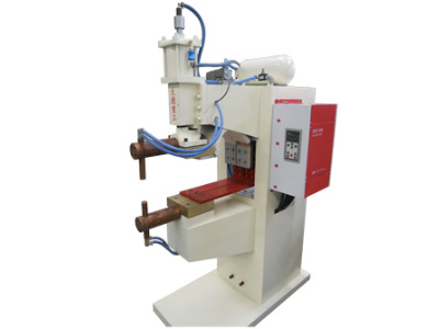
For sheet assemblies joined by overlapping flanges — panels, brackets, housings — resistance welding is faster and cheaper per joint than arc welding, with no filler and no fume. Dade Heavy Industry's DN series pneumatic spot welding machines cover the band from thin sheet to 7 mm total thickness.
|
Model |
Rated capacity |
Input current |
Electrode extension |
Welding thickness |
|
DN-25 |
25 kVA |
65 A |
350 mm |
0.5+0.5 to 3+3 mm |
|
DN-50 |
50 kVA |
131 A |
520 mm |
1+1 to 4.5+4.5 mm |
|
DN-75 |
75 kVA |
197 A |
560 mm |
1+1 to 5+5 mm |
|
DN-100 |
100 kVA |
263 A |
560 mm |
1.5+1.5 to 6+6 mm |
|
DN-150 |
150 kVA |
395 A |
560 mm |
1.5+1.5 to 7+7 mm |
All run single-phase 380 V at 50 Hz with a 50 percent duty cycle. Electrode extension distance is the number that decides whether the machine can reach the joint on a deep panel; 350 mm is fine for a flat cover, 560 mm is needed when the flange sits inside a formed box.
The same family extends to projection welding (DT series) for nuts, studs and bosses, and to seam welding (FN and FNZ series) for leak-tight longitudinal joints, including narrow lap seam welding for steel strip.
Arc welding for structural work
Above roughly 3 mm total thickness on a structural joint, arc welding takes over. MIG with a controlled short-circuit waveform covers 1.2 to 8 mm efficiently; submerged arc covers long straight seams on thick plate; flux-cored wire covers site work and outdoor conditions where gas shielding is impractical.
The 1.2–5.0 mm Band in Practice
This band is where most
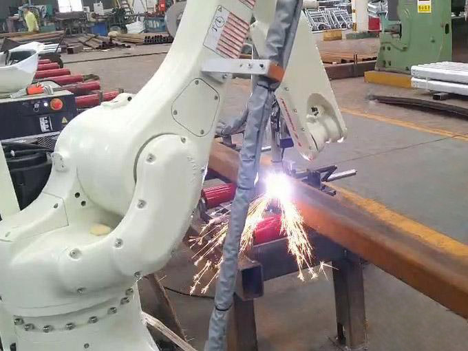
robotic carbon steel welding happens, and it is where a low-spatter source earns its keep. Dade's horizontal rotation welding workstation is specified for Q195 and Q235 plate from 1.2 to 5.0 mm with a 350 A low-spatter source, a current range of 30 to 350 A, welding speed of 0.3 to 1.0 m/min and a working range of ±165°.
Two numbers in that specification deserve attention. The 30 A lower limit is what makes 1.2 mm possible without burn-through. The ±165° range is what allows a part to be welded from both sides without reclamping, which halves the handling time and removes the repositioning error that shows up as a mismatched seam.
Power Source Sizing
|
Plate thickness |
Current |
Wire diameter |
Gas |
|
1.2–2.0 mm |
60–110 A |
0.8 mm |
92/8 Ar/CO₂ |
|
2.0–4.0 mm |
110–200 A |
1.0 mm |
85/15 Ar/CO₂ |
|
4.0–6.0 mm |
180–260 A |
1.2 mm |
80/20 Ar/CO₂ |
|
6.0–10 mm |
240–320 A |
1.2 mm |
80/20 Ar/CO₂ |
|
10 mm and up |
300 A+ |
1.2–1.6 mm |
CO₂ or 80/20 |
Duty cycle decides the frame size. A 350 A machine at 60 percent duty will not run at 350 A continuously. For a robotic cell with high arc-on time, specify a source rated for the actual duty or derate the current by 15 to 20 percent.
Consumables and Cost Per Metre
|
Item |
Consumption per metre of fillet |
Note |
|
Wire, 1.2 mm |
0.35–0.55 kg |
Depends on leg length |
|
Gas, 80/20 |
0.15–0.25 m³ |
At 15–18 l/min and 0.5 m/min |
|
Contact tip |
1 per 8–12 h arc time |
Count, don't wait for failure |
|
Nozzle |
1 per 2–4 weeks |
Cleaning extends life |
|
Power |
0.25–0.4 kWh |
At 200 A |
Add labour and cleaning, and a 6 mm fillet lands somewhere between 12 and 25 CNY per metre depending on the shop. The spread is wide because cleaning and rework vary more than the welding itself.
Thick Plate and Pressure Boundaries
High-voltage motor casings are a useful example of carbon steel work where the weld is also a sealing and insulation boundary. The process requirements are material properties, structural robustness, hermetic sealing and electrical insulation performance, and the weld locations are defined by drawing rather than by operator judgement. Dade Heavy Industry builds welding systems for this application with the workstation layout developed around the specified weld positions.
On thick carbon steel, three controls prevent most failures: preheat per the procedure for the grade and thickness, interpass temperature limits, and hydrogen control through dry consumables and clean joint faces.
Common Defects and Their Causes
• Porosity: wet electrode, contaminated gas, oil on the plate, or a leaking gas hose
• Lack of fusion: travel too fast, current too low, or torch angle pushing the arc onto the wrong plate
• Undercut: current too high or travel angle too steep
• Distortion: unbalanced sequence, no backing bar, or too much heat per pass
• Spatter adhesion: gas mix, stick-out, or a worn contact tip
Each has a measurable cause. A welding procedure that lists current, voltage, travel speed, gas flow and stick-out gives the operator something to check when a defect appears.
Verifying on Your Parts
Run a first-article weld on the thinnest and thickest joint in the family, section it, and measure penetration and leg length. Then run 30 parts and check spatter count, distortion and cycle time. For resistance welding, do a peel test and a nugget diameter measurement on the first and last part of each shift, because electrode wear changes the nugget before anything visible changes.
Working With Dade Heavy Industry
Dade Heavy Industry (stock code 870547) covers carbon steel from both sides of the process divide: resistance welding machines from 25 kVA to 150 kVA in spot, projection and seam configurations, and arc welding systems built into robotic workstations and production lines. The company operates a 100,000 m² plant in Wuxi, Jiangsu with roughly 600 employees, holds IATF and ISO management system certifications, and has delivered close to 10,000 sets across 50 series and 200 specifications to customers in 30 Chinese provinces and export markets including Southeast Asia, the Middle East, Japan, Europe and the Americas.
Its carbon steel references range from a 350 A low-spatter station for 1.2 to 5.0 mm plate to a gas-shielded robotic line welding high-voltage motor casings, and to wheel rim lines running FANUC robots with Fronius sources. That spread is the practical argument for buying from a supplier who builds both resistance and arc equipment: the recommendation follows the joint rather than the product catalogue.
Before you specify a carbon steel welding machine, fix the thickness band, the joint type and the annual volume. Those three answers eliminate most of the market, and the remaining choice is between machines that can all do the job.