Why Does Fixture Design Determine Robotic Welding Quality?
Fixture design determines whether a robot sees the same joint in the same place on every cycle. A welding robot can repeat a programmed path very accurately, but it cannot compensate for uncontrolled part variation, poor locating, clamp deflection, or thermal movement unless the cell includes suitable sensing and correction.
Manual welders continuously adapt torch angle, stickout, travel speed, and aim point. A robot follows a defined coordinate path. If a joint shifts outside the process window, the robot may still complete the cycle while producing undercut, incomplete fusion, burn-through, inconsistent penetration, or a weld in the wrong location.
Fixture engineering therefore links product design, incoming-part tolerances, welding process capability, and robot programming. Treating the fixture as a secondary mechanical accessory usually creates expensive downstream problems: repeated touch-ups, long teaching time, unstable cycle time, and unexplained quality drift.
What Is a Datum Strategy for a Welding Fixture?
A datum strategy defines the surfaces and features that establish a part’s position in three-dimensional space. For most rigid components, the classic 3-2-1 locating principle provides a useful starting point: three points establish the primary plane, two points establish the secondary direction, and one point constrains the final degree of freedom.
The principle is simple, but production fixtures require engineering judgment:
Select functional datums that matter to the finished assembly, not merely surfaces that are easy to contact.
Avoid locating from rough flame-cut edges, weld beads, scale, or flexible sheet unless the variation is intentionally accommodated.
Keep locators far enough apart to create a stable base, while avoiding areas likely to distort during welding.
Use pins, nests, rest pads, V-blocks, or profiled locators according to part geometry.
Make wear components replaceable and reference their position from machined fixture features.
Over-location is a common failure. When too many rigid locators attempt to constrain the same degree of freedom, normal dimensional variation prevents parts from seating consistently. The operator then forces the component into the fixture, creating stored stress that is released after unclamping.
How Should Clamping Force Be Selected?
Clamping force should be high enough to keep parts seated against their locators, but not so high that it bends the workpiece or masks a dimensional problem. More force is not automatically better. Thin sheet, tubular structures, and long fabricated parts can deform under pneumatic or hydraulic clamps before the arc starts.
A practical clamp design considers five factors:
Direction of force: The clamp should push the part into the locating system rather than sideways across it.
Distance from the locator: Large offsets create bending moments and fixture deflection.
Part stiffness: Flexible areas may need distributed pads, backup support, or controlled low-pressure clamping.
Weld reaction and thermal movement: Clamps must resist process forces while allowing a planned release path for expansion.
Failure state: Loss of air or hydraulic pressure must not create an unsafe drop, ejection, or collision condition.
Pneumatic clamps are fast and clean for many assemblies. Hydraulic clamps provide higher force density but require additional leak and maintenance control. Servo or electrically actuated clamps can add programmable position and force feedback when mixed-model production requires multiple recipes.
How Can a Fixture Reduce Welding Distortion?
A fixture reduces distortion by controlling joint fit-up, heat sequence, restraint, and the release of residual stress. It cannot eliminate thermal expansion. If the fixture restrains every direction rigidly, the part may spring out of tolerance as soon as clamps open.
Effective distortion control usually combines mechanical and process measures:
Balance welds around the neutral axis where the product design permits.
Use back-step, skip, or symmetrical sequences instead of depositing all heat from one side.
Minimize unnecessary weld volume by matching joint design to load requirements.
Place clamps close enough to the joint to control fit-up without blocking the torch.
Provide expansion direction through sliding locators, relieved pins, or timed clamp release.
Use copper chill bars or heat sinks only where metallurgical and access conditions make them appropriate.
Confirm whether the process should weld from the center outward or from restrained zones toward free ends.
The welding sequence belongs in the fixture design review. A fixture designed before the sequence is known often puts clamps, cylinders, and frame members in the robot’s preferred approach path.
How Much Clearance Does a Welding Robot Need?
Clearance must cover the complete motion envelope of the torch, wrist, cable package, seam sensor, reamer access, and part-loading equipment. Checking only the nominal tool center point path is insufficient because the robot wrist and dress pack sweep a much larger volume.
|
Design Area |
What Must Be Verified |
|
Torch angle |
Required work angle and travel angle along the entire joint |
|
Stickout |
Stable contact-tip-to-work distance without clamp interference |
|
Wrist posture |
No singularity, axis limit, or unnecessary wrist flip |
|
Cable package |
No snagging, over-bending, or repeated contact with the fixture |
|
Cleaning station |
Unobstructed movement to nozzle cleaning, wire cutting, and anti-spatter functions |
|
Service access |
Replacement of tips, liners, sensors, pins, and clamps without dismantling the fixture |
Offline simulation can identify many collisions before fabrication, but the model must include real clamp bodies, hoses, cable routing, sensor brackets, and loading devices. Simplified geometry creates false confidence.
Which Materials and Surfaces Work Best for Fixtures?
Fixture materials should provide dimensional stability, wear resistance, repairability, and appropriate electrical and thermal behavior. Welded structural-steel bases are common, but precision locator plates and pin bores normally require machining after stress relief.
Typical choices include hardened tool-steel pins for repeated hole location, replaceable wear pads for high-load contact surfaces, copper-alloy backing where heat extraction is required, and insulating bushes where unintended welding-current paths could damage bearings or sensors.
Spatter accumulation changes locator height and clamp seating. Surfaces near the arc should minimize horizontal shelves and inaccessible pockets. Protective covers, sacrificial shields, and a defined cleaning interval are often more valuable than elaborate coatings.
How Should Sensors Be Integrated into the Fixture?
Sensors should confirm the conditions required for a safe and valid cycle, not simply generate more data. A robust fixture commonly verifies part presence, clamp open/closed state, correct model selection, and critical locator seating.
Useful sensing options include inductive proximity sensors, mechanical switches, pressure switches, analog clamp-position sensors, vision systems, and laser profile sensors. The sensor should measure the actual production condition. A cylinder-end switch confirms cylinder travel, for example, but may not prove that the part is seated against the datum.
Safety-related sensing and interlocking should be engineered separately from ordinary process confirmation. Applicable requirements may include ISO 10218 for industrial robot systems and ISO 13849-1 for safety-related control functions.
What Should Be Checked During Fixture Acceptance?
Fixture acceptance should prove repeatability with production-like parts, not just demonstrate that one carefully selected assembly can be welded. A useful acceptance plan tests the fixture across the expected tolerance range and operating conditions.
Fixture Acceptance Checklist
Datum scheme matches the product drawing and functional assembly requirements.
Parts load without forcing, hammering, or ambiguous orientation.
Clamps seat parts without measurable pre-weld deformation.
All welds maintain required torch angle, stickout, and access.
Robot paths avoid singularities and collisions at each positioner angle.
Sensors detect missing, reversed, or incorrectly seated components.
Spatter protection and cleaning access are practical.
Gauge studies confirm repeatable part location.
First-off and warm-fixture parts remain within dimensional requirements.
Clamp release sequence does not cause uncontrolled spring-back.
Preventive-maintenance items are identified and accessible.
Run-at-rate testing is essential because heat accumulation, operator loading behavior, and spatter buildup may not appear during a short demonstration.
How Does Fixture Design Affect Automation ROI?
Good fixture design increases ROI by reducing teaching, touch-up, scrap, loading variation, and unplanned downtime. The fixture may represent a modest share of total cell cost, but it controls much of the cell’s usable availability.
For high-mix production, quick-change nests, keyed connections, recipe-controlled clamps, and automatic model verification can reduce changeover time. For high-volume production, durability, mistake-proofing, parallel loading, and rapid service access usually matter more than maximum flexibility.
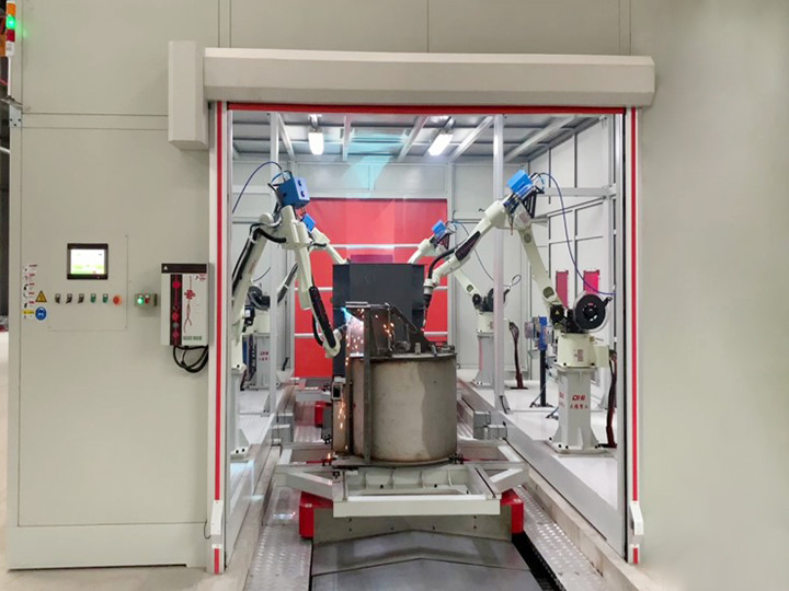
JiangSu Dade Heavy Industry develops robotic welding workstations and related automation systems for fabricated components. Buyers should review the robot, welding source, positioner, fixture, sensing, guarding, and loading method as one integrated production system rather than purchasing each element in isolation.
Frequently Asked Questions
What is the most common robotic welding fixture mistake?
The most common mistake is assuming that robot repeatability can compensate for inconsistent part location. A repeatable robot will repeat the same incorrect relationship if the fixture allows the joint to move.
Should a welding fixture hold the part as rigidly as possible?
No. It should hold the part firmly enough to maintain fit-up while providing a controlled way for thermal expansion and residual stress to develop. Excessive restraint can increase spring-back after unclamping.
When is seam tracking still required with a good fixture?
Seam tracking is useful when incoming-part tolerances, long joints, forming variation, or thermal movement exceed the welding process window. It complements a capable fixture; it does not replace one.
How often should fixture locators be checked?
The interval should be based on cycle count, wear rate, contamination, and quality risk. High-wear pins and pads may require daily visual checks and scheduled dimensional verification.
Can one fixture support multiple product models?
Yes, if datum relationships, clamp positions, sensing, and robot recipes are designed for controlled changeover. Interchangeable nests should include positive identification to prevent the wrong program from running.
Conclusion
Robotic welding fixture design is a production-engineering discipline, not merely a fabrication task. Stable datums, appropriate clamp force, managed thermal movement, complete tool access, meaningful sensing, and maintainable construction create the conditions in which a robot can deliver consistent welds. The correct acceptance question is not, “Can the fixture hold the part?” It is, “Can the entire cell repeatedly produce conforming assemblies at the required rate?”