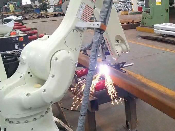
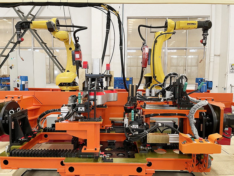
What Is Robotic Weld Seam Tracking?
Robotic weld seam tracking is a closed-loop method for locating a real joint and correcting the robot’s nominal path. It bridges the gap between programmed geometry and production reality caused by part tolerances, fixture variation, forming error, thermal distortion, and inconsistent tack welds.
Seam-sensing systems perform one or both of two functions:
Seam finding measures the joint before the weld begins and shifts the programmed path.
Real-time tracking measures the joint or arc condition during welding and continuously adjusts the tool center point.
These functions solve different problems. A pre-weld search can correct a global offset, but it cannot follow a long joint that curves away from the nominal path. Real-time tracking can follow gradual movement, but it is not a substitute for correct part loading or a fixture that allows excessive discontinuities.
Why Is Robot Repeatability Not Enough?
Robot repeatability describes how consistently the robot returns to a commanded position; it does not describe where the joint is located. Even a highly repeatable robot can miss a seam when stamped, rolled, cut, or manually tacked components vary.
The total path error can include robot and tool calibration error, fixture locator wear, part dimensional variation, gap and mismatch variation, thermal movement, positioner calibration error, and tack-weld inconsistency. The process window determines how much error is acceptable. A wide fillet weld may tolerate more aim variation than a narrow laser-welded butt joint.
Seam tracking should therefore be selected from the joint and process requirements, not added as a generic upgrade.
How Does Touch Sensing Work?
Touch sensing uses the welding wire, gas nozzle, or a dedicated probe to make electrical or mechanical contact with the workpiece before welding. The robot searches for known features, records contact positions, and shifts the weld path or work-object coordinate system.
Advantages of Touch Sensing
Uses existing welding hardware in many gas metal arc welding cells.
Requires limited additional equipment.
Works well for finding edges, plate surfaces, corners, and joint start points.
Can correct translation and, with enough search points, rotation.
Is relatively insensitive to ambient light.
Limitations of Touch Sensing
Adds non-welding search time to the cycle.
Requires conductive, reasonably clean surfaces when using the wire.
Can false-trigger through spatter, scale, or bent wire.
Measures discrete points rather than the full seam profile.
Does not normally correct rapid path variation during welding.
Wire cutting and nozzle cleaning are important because a bent wire changes the contact point. Search speed, contact debounce, and approach direction should be standardized in the robot program.
How Does Through-Arc Seam Tracking Work?
Through-arc seam tracking uses changes in welding current or voltage as the torch weaves across the joint. When the electrode moves closer to one sidewall, electrical conditions change. The controller compares signals from both sides of the weave and shifts the robot toward the joint center.
Through-arc sensing is useful for fillet, groove, and multi-pass arc welds where a measurable sidewall relationship exists.
Strengths
Tracks during welding instead of adding a separate search pass.
Uses process signals already available from the welding power source.
Tolerates smoke and moderate contamination better than many optical methods.
Can support multi-pass bead placement where groove geometry is suitable.
Constraints
Usually requires a weaving motion.
Performance depends on stable wire feed, stickout, transfer mode, and electrical contact.
Thin sheet and high-speed straight welds may provide insufficient signal.
It cannot correct abrupt joint jumps safely.
Signal filtering must distinguish geometry-related changes from spatter, short circuits, unstable transfer, and cable-resistance variation.
How Does Laser Vision Seam Tracking Work?
Laser vision projects a line or pattern across the joint and uses a camera to calculate the seam profile in three dimensions. The sensor can measure joint center, gap, mismatch, groove angle, and other geometric features before or during welding.
Laser vision is selected when the application requires more information than touch or through-arc sensing can provide. It can inspect ahead of the torch, generate path correction, and sometimes adjust process parameters according to measured gap.
Advantages
Non-contact measurement at production speed.
Continuous profile data instead of isolated search points.
Support for complex joints and adaptive process control.
Joint-geometry records for traceability.
No need for the welding wire to touch the part.
Challenges
Higher equipment and integration cost.
Exposure to heat, spatter, smoke, and vibration.
Reflective surfaces require optical-filter and exposure optimization.
Calibration between sensor, robot, torch, and work coordinates must remain stable.
Sensor look-ahead distance limits operation near corners and seam ends.
Protective windows need an air knife or scheduled cleaning. A dirty window may still return data, but with lower confidence and higher noise.
Which Seam-Tracking Method Should You Choose?
Choose the least complex method that reliably keeps the joint inside the validated process window. A comparison should include correction capability, cycle time, process compatibility, maintenance, and data requirements.
|
Criterion |
Touch Sensing |
Through-Arc Sensing |
Laser Vision |
|
Measurement timing |
Before welding |
During welding |
Before or during welding |
|
Typical process |
Arc welding |
Arc welding |
Arc or laser welding |
|
Data type |
Discrete contact points |
Electrical process signal |
Continuous joint profile |
|
Handles gradual seam drift |
Limited |
Yes |
Yes |
|
Measures gap and mismatch |
No |
Indirectly |
Yes |
|
Added cycle time |
Moderate |
Low |
Low to moderate |
|
Main sensitivity |
Wire condition and surface contact |
Arc stability and weave geometry |
Optics and reflectivity |
|
Integration complexity |
Low |
Medium |
High |
A hybrid system is common. Touch sensing may establish the starting offset, while through-arc tracking follows the weld. Laser vision may scan the seam and feed adaptive parameters to the welding controller.
Which Applications Fit Each Technology?
Joint geometry and production behavior determine the best fit. The following examples provide a practical starting point.
Touch Sensing Fits
Large fabricated frames with clear plate edges.
Moderate-volume arc welding where a few searches do not limit throughput.
Components with overall fixture offset but stable local geometry.
Applications seeking low-complexity correction.
Through-Arc Tracking Fits
Long fillet or groove welds.
Structural fabrications with gradual plate movement.
Multi-pass arc welding where bead placement must follow a groove.
Cells already using controlled weave welding.
Laser Vision Fits
Variable gaps and mismatch requiring geometric measurement.
High-speed joints where contact search is too slow.
Laser welding with a narrow process window.
Mixed-model production with several joint profiles.
Applications requiring seam data and traceability.
No sensor should be expected to correct missing, reversed, or grossly misplaced parts. Those conditions belong to fixture mistake-proofing and part-presence verification.
How Is a Seam-Tracking System Calibrated?
Calibration establishes the relationship between sensor measurement, robot coordinates, tool center point, and the real joint. Small calibration errors can become large path errors when the sensor is far ahead of the torch or the robot changes orientation.
A practical sequence is:
Calibrate the robot tool center point.
Verify the work-object or fixture coordinate system.
Calibrate the sensor relative to the robot flange or torch.
Measure the sensor-to-torch look-ahead geometry.
Run a known reference coupon and compare measured versus actual features.
Verify performance at representative robot and positioner angles.
Store baseline results for maintenance comparison.
Recheck calibration after a torch crash, sensor replacement, bracket adjustment, robot mastering event, or unexplained quality shift.
What Causes Seam-Tracking Failures?
Most failures come from poor signal quality, incorrect calibration, process instability, or correction limits that do not match real variation. The system may appear functional while producing noisy or delayed corrections.
Common failure modes include spatter on the touch wire or optical window, bent wire after cutting, arc instability interpreted as movement, saturated camera images, bracket movement after a collision, incorrect seam templates, and correction settings that cause path oscillation.
Diagnostics should record sensor confidence, applied offsets, process alarms, and rejected scans. Trend data can reveal a deteriorating condition before weld defects rise.
How Should Seam Tracking Be Validated?
Validation must show that the fixture, sensor, robot, and welding process produce acceptable welds across the real tolerance range. Demonstrating the sensor on one ideal coupon is not sufficient.
Test parts should represent minimum and maximum gap, mismatch, offset, surface condition, and expected distortion. Confirm search repeatability, maximum safe correction, response through curves, cycle-time effect, weld quality at extremes, recovery when confidence is lost, and reject logic.
Weld acceptance should follow the drawing, welding procedure, and applicable quality standard. ISO 5817 is frequently used to classify imperfections in fusion-welded joints, but the required acceptance level depends on the product and contract.
How Does Seam Tracking Fit into a Dade Welding Cell?
Seam tracking should be integrated as part of the complete cell architecture. Robot reach, torch package, positioner, fixture, welding source, PLC, safety system, and data collection all influence the result.
JiangSu Dade Heavy Industry supplies robotic welding workstations and robot laser welding systems. Buyers should provide representative parts, tolerance data, joint drawings, target cycle time, welding procedures, and acceptance criteria. This allows the sensing method to be validated against actual variation rather than selected from a brochure description.
Frequently Asked Questions
Can seam tracking replace a welding fixture?
No. It corrects controlled variation; it does not provide structural support, orientation, gap control, or safe loading.
Is laser vision always more accurate than touch sensing?
Laser vision provides more information, but practical accuracy depends on calibration, reflectivity, optical cleanliness, mounting rigidity, and software. Touch sensing may be more reliable for a simple conductive edge.
Does through-arc tracking work without weaving?
Most implementations need a lateral weave to compare electrical conditions on both sides. A straight path usually provides less directional information.
How far can a robot correct its path?
The safe limit is application-specific. It must remain within robot motion, torch access, joint design, fixture clearance, and qualified process limits. Large offsets should trigger a fault.
Can seam tracking adjust welding parameters too?
Some laser vision systems can measure gap or groove area and command travel speed, wire feed, weave, or power within qualified limits.
Conclusion
Robotic weld seam tracking is most effective when it addresses a defined source of variation. Touch sensing offers simple pre-weld location, through-arc sensing follows suitable arc-weld joints during the process, and laser vision supplies continuous geometry for demanding applications. The objective is not to add the most advanced sensor. It is to keep every joint inside a validated process window with predictable cycle time, maintenance, and fault handling.