Why Are Hot-Formed Parts Laser Trimmed?
Hot-formed, or press-hardened, components are laser trimmed because the final part is strong, three-dimensional, and often produced in several evolving variants. Laser processing follows a programmable path and applies no mechanical cutting force, reducing the need for dedicated high-force trim dies.
Press hardening typically heats a boron-alloy steel blank, forms it in a cooled die, and transforms it into a high-strength component. The formed part may then need perimeter trimming, holes, slots, and datum features. These operations must follow the actual three-dimensional surface.
Typical components include body pillars, roof rails, rockers, door-impact structures, bumper reinforcements, and other crash-relevant parts. Exact material and coating systems vary by vehicle program, so cutting trials must use production-representative parts.
Robot Cell or Five-Axis Machine?
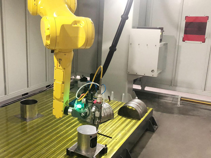
A robot cell offers a large flexible work envelope, while a dedicated five-axis laser machine generally emphasizes path accuracy, dynamic control, and process enclosure. The correct choice depends on tolerance, part size, cycle time, mix, loading concept, and investment strategy.
|
Criterion |
Robot-Based 3D Cutting |
Dedicated Five-Axis Machine |
|
Work envelope |
Large and adaptable |
Defined by machine architecture |
|
Flexibility |
High for mixed large parts |
High within specified envelope |
|
Path performance |
Depends on robot calibration and posture |
Optimized machine kinematics |
|
Integration |
Flexible with positioners and handling |
Highly integrated process platform |
|
Typical value |
Complex large parts and reconfigurable cells |
Tight, repeatable high-speed contouring |
A robot solution can be highly capable when the path avoids weak postures and the cell includes appropriate calibration and standoff control. Equipment selection should be based on a measured capability study, not the axis count alone.
How Should a 3D Cutting Fixture Locate the Part?
The fixture should locate the hot-formed part from stable functional features while accommodating normal forming variation without forcing the component into a false shape. Over-constraining a thin shell can make the cut appear accurate in the fixture but wrong after release.
Good fixture practice includes:
Use widely spaced, repeatable support points.
Locate from features that survive the forming process consistently.
Keep clamps away from the cutting head and assist-gas plume.
Support near piercing locations where local vibration or ejection is possible.
Provide drop clearance for slugs and trim scrap.
Prevent hot scrap from damaging hoses, sensors, or locator surfaces.
Detect incorrect loading and model mismatch.
If part variation exceeds the cut tolerance, add measurement or adaptive correction. A fixture cannot make an unstable forming process disappear.
Why Is Nozzle Standoff Critical?
Nozzle standoff controls assist-gas flow, focus relationship, collision clearance, and cut consistency over a three-dimensional surface. As the head changes orientation, the surface normal and local geometry change continuously.
Capacitive height sensing is common on conductive materials, but its response can be affected by edges, holes, steep curvature, coatings, and nearby fixture metal. The motion system needs a strategy for entering and leaving height control, crossing discontinuities, and recovering after a lost signal.
The nozzle should remain aligned with the intended cut direction while avoiding excessive angular error. A path that looks correct at the focal point can still place the nozzle body close to flanges or clamps. Simulate the complete head geometry and verify it physically at reduced speed.
How Are Piercing and Cut Starts Controlled?
Piercing requires a controlled sequence because the laser initially interacts with a closed surface and must eject molten material without damaging the nozzle or surrounding part. Start conditions differ from steady-state cutting.
Variables include pierce power, pulse or ramp strategy, dwell time, focus, gas pressure, nozzle distance, lead-in geometry, and the material’s coating. A pierce placed directly on the final contour may leave a visible notch or dimensional defect. Where design permits, use a lead-in from scrap material.
For small holes, the relationship between hole diameter, material thickness, beam size, and machine dynamics becomes critical. If the feature is near the capability limit, validate roundness, taper, heat-affected zone, and positional accuracy rather than assuming a programmed circle produces a compliant hole.
Which Assist Gas Should Be Used?
Assist gas ejects molten material and influences oxidation, edge chemistry, heat input, and cutting speed. Oxygen can provide an exothermic contribution for some steels, while nitrogen or another inert approach may be chosen when oxidation must be limited.
The selection depends on material, coating, thickness, edge-quality requirement, downstream joining, and cost. Gas pressure at the source does not prove stable flow at the nozzle. Line restrictions, valve response, nozzle damage, and leaks affect delivery.
Define acceptable dross, oxide, edge roughness, and discoloration from the requirements of the next process. An edge that is visually acceptable may still be unsuitable for adhesive bonding, welding, coating, or dimensional assembly.
How Do Coatings Affect Cutting?
Coatings can change absorption, vapor generation, spatter, edge chemistry, and sensor response. Aluminum-silicon-coated press-hardened steels, zinc-based coatings, and uncoated materials should not be treated as equivalent.
Coating behavior may influence pierce stability and create deposits on optics-protection components. It may also affect fumes and extraction requirements. Process trials should include the full coating-thickness range and realistic surface conditions.
Never rely on a material family name alone. Record the steel grade, coating system, batch information, thickness, and forming condition used during qualification.
How Is Dimensional Accuracy Maintained?
Dimensional accuracy requires control of part location, path calibration, tool geometry, thermal stability, and motion posture. Error can come from the part, fixture, robot, scanner, external axis, CAD conversion, or measurement method.
A robust control plan includes:
Robot or machine kinematic verification.
Cutting-head tool-center and orientation calibration.
Fixture coordinate calibration using traceable datums.
Reference-part or artifact checks at defined intervals.
Path verification at representative orientations.
Periodic dimensional measurement of trimmed parts.
Trend monitoring for drift before tolerance is exceeded.
Offline programming is valuable, but the digital model must match the physical cell. Shop-floor corrections should be fed back into the master model.
What Cut Defects Should Be Monitored?
Cut defects reveal different combinations of energy, gas, focus, motion, and material problems. A defect catalogue should link appearance to likely causes and approved reactions.
Common issues include dross, incomplete separation, excessive bevel, rough striations, top-edge melting, backside burn, pierce spatter, hole taper, contour mismatch, and local heat distortion. For each, inspect nozzle condition, centering, focus, protective window, power, gas, speed, standoff, and part position.
Do not compensate for a damaged nozzle by changing the production recipe. Verify hardware first, then adjust process variables through controlled change management.
How Should the Cell Be Validated for Automotive Production?
Validation should demonstrate capability on the full product family at production rate and across expected material and forming variation. It should include dimensional, process, safety, and traceability requirements.
Recommended evidence includes:
Gauge repeatability and reproducibility for critical dimensions.
Capability studies for holes, slots, and trimmed datums.
Run-at-rate results including loading and scrap removal.
Cut-quality samples at parameter boundaries.
Recovery tests for gas, sensor, laser, and motion faults.
Verification of part and recipe identification.
Extraction performance and fire-risk controls.
Preventive-maintenance and calibration plans.
JiangSu Dade Heavy Industry supplies robotic 3D laser cutting and trimming systems. Customers should provide final CAD, tolerance drawings, annual mix, material and coating data, cycle-time target, inspection plan, and representative formed parts before acceptance criteria are finalized.
Frequently Asked Questions
Can flat blanks be fully cut before hot forming?
Some features can be pre-cut, but forming changes geometry and can distort or damage edges and holes. The manufacturing plan must determine which features require final trimming after forming.
Does laser cutting reduce the need for fixtures?
No. It removes cutting force but still requires repeatable part location and stable support. Accuracy follows the relationship between the part, fixture, and motion system.
Can a robot cut every surface angle?
Only if reach, wrist posture, cable routing, nozzle orientation, standoff sensing, and collision clearance remain acceptable. Simulation and physical verification are required.
Why does dross increase during a long production run?
Possible causes include nozzle wear, protective-window contamination, focus drift, gas restriction, hotter fixtures, coating variation, or part-position drift. Trend process and maintenance data together.
How should trim scrap be handled?
Design chutes, bins, guarding, and sensors so slugs cannot accumulate, rebound into the process, damage equipment, or create a fire hazard.
Conclusion
3D laser cutting gives automotive manufacturers a programmable way to finish strong, complex hot-formed parts. Production success depends on much more than laser power: part location, standoff control, piercing, gas delivery, calibrated motion, coating behavior, scrap handling, and dimensional validation all determine capability. The best cell is one that holds its cut quality across the real forming and material variation of the vehicle program.